
STANDARD 2
STANDARD 2 Tube Diffusers

| STANDARD 2 Tube Diffusers | ||||||||
|---|---|---|---|---|---|---|---|---|
| B: Overall length, installed | C | D | Material | |||||
| STANDARD 2 500 | STANDARD 2 750 | STANDARD 2 1000 | ||||||
| STANDARD 2 for 45 mm / 1.8" hole | 528 mm / 20.8" | 780 mm / 30.7" | 1030 mm / 40.6" | Ø 63 mm /2.5" | Ø ¾" BSP | PP | ||
| STANDARD 2 for 40 mm / 1.6" hole | 528 mm / 20.8" | 780 mm / 30.7" | 1030 mm / 40.6" | Ø 63 mm /2.5" | Ø ¾" BSP | PP | ||
| STANDARD 2 for 30 mm hole | 528 mm / 20.8" | 780 mm / 30.7" | 1030 mm / 40.6" | Ø 63 mm / 2.5" | Ø ¾" BSP | PP | ||
| Active membrane surface | 0,08 m² / 0.9 ft² | 0,12 m² / 1.3 ft² | 0,16 m² / 1.7 ft² | |||||
| A Active membrane length | 480 mm / 18.9" | 730 mm / 28.7" | 980 mm / 38.6" | |||||
| Weight/diffuser | 1,0 kg / 2.2 lbs | 1,2 kg / 26.5 lbs | 1,4 kg / 30.9 lbs | |||||
| Buoyancy in operation / diffuser | 0,5 kg / 11,0 lbs | 0,7 kg / 15.4 lbs | 1,0 kg / 2.2 lbs | |||||
Adapter Sleeve for 45 mm Hole

| Adapter sleeve for 45 mm hole | ||||
|---|---|---|---|---|
| Article designation | Article number | A | B | Material |
| Adapter sleeve for 45 mm / 1.8" hole | 4251000045 | Ø 44 mm / 1.7" | 24,5 mm / 9.6" | PP-GF |
Adapter Sleeve for 40 mm Hole

| Adapter sleeve for 40 mm hole | ||||
|---|---|---|---|---|
| Article designation | Article number | A | B | Material |
| Adapter sleeve for 40 mm / 1.6" hole | 4251000040 | Ø 39 mm / 1.5" | 24,5 mm / 9.6" | PP-GF |
¾″ Connectors

| ¾″ connectors for mounting of STANDARD 2 tube diffuser pair on lateral | ||||||
|---|---|---|---|---|---|---|
| Article designation | Article number | A | D | E | Thread | Material |
| VB 80 PP ST 2 | 4210801200 | 138mm / 5.4" | Ø 26,9mm / 1.05" | 25mm / 1" | ¾" BSP | PP-GF |
| VB 100 PP ST 2 | 4211001200 | 158 mm / 6.2" | Ø 26,9 mm / 1.05" | 25 mm / 1" | ¾" BSP | PP-GF |
| VB 120 PP ST 2 | 4211201200 | 176 mm / 6.9" | Ø 26,9 mm / 1.05" | 25 mm / 1" | ¾" BSP | PP-GF |
| VB 60 Stainless V4A ST 2 | 4210601400 | 118 mm / 4.65" | Ø 26,9 mm / 1.05" | 27 mm / 1.06" | ¾" BSP | V4A |
| VB 80 Stainless V4A ST 2 | 4210801400 | 138 mm / 5.4" | Ø 26,9 mm / 1.05" | 27 mm / 1.06" | ¾" BSP | V4A |
| VB 100 Stainless V4A ST 2 | 4211001400 | 158 mm / 6.2" | Ø 26,9 mm / 1.05" | 27 mm / 1.06" | ¾" BSP | V4A |
| VB 120 Stainless V4A ST 2 | 4211201400 | 176mm / 6.9" | Ø 26,9mm / 1.05" | 27mm / 1.06" | ¾" BSP | V4A |
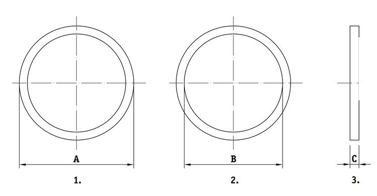
Gaskets

| Gaskets | |||||
|---|---|---|---|---|---|
| Article designation | Article number | A | B | C | Material |
| STANDARD 2 gasket for 40 mm / 45 mm hole (1.6"/1.8") | 4242000002 | Ø 60 mm / 2.4" | Ø 39 mm / 1.5" | 2,5 mm / 0.1" | EPDM |
| STANDARD 2 gasket for 30 mm hole (1.2") | 4242000003 | Ø 60 mm / 2.4" | Ø 29 mm / 1.14" | 2,5 mm / 0.1" | EPDM |
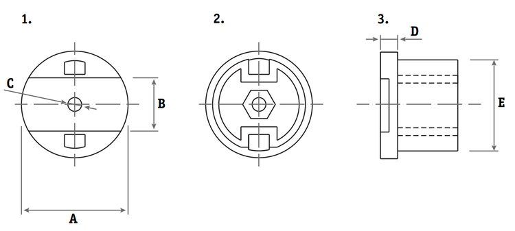
Dummy plugs
| Dummy plugs for different lateral holes | |||||||
|---|---|---|---|---|---|---|---|
| Article designation | Article number | A | B | C | D Thread | Material | |
| Dummy plug for 30 mm hole (1.2") | 4230000030 | Ø 60mm / 2.4" | Ø 44mm / 1.7 | 42mm / 1.6" | ¾” BSP | PP-GF | |
| Dummy plug for 40 mm hole | 4230000333 | Ø 60mm / 2.4" | Ø 39mm / 1.5" | 42mm / 1.6" | ¾” BSP | PP-GF | |
| Dummy plug for 45 mm hole (1.2") | 4230000022 | Ø 60 mm / 2.4" | Ø 44 mm / 1.7" | 42 mm / 1.6" | ¾” BSP | PP-GF | |

Gaskets for Dummy Plugs
- Front view
- Rear view
- Side view
| Gasket for Dummy Plug | |||||
|---|---|---|---|---|---|
| Article designation | Article number | A | B | C | Material |
| Gasket for 30 mm hole (1.2") | 4242000006 | Ø 63mm / 2.5" | Ø 43mm / 1.7 | 9mm / 0.35" | EPDM |
| Gasket for 40 mm hole (1.6") | 4242000000 | Ø 63 mm / 2.5" | Ø 40 mm / 1.6" | 4 mm / 0.16" | EPDM |
| Gasket for 45 mm hole | 4241000000 | Ø 63 | Ø 43 | 4 | EPDM |
Saddle Adapters

| Saddle Adapters | |||||||
|---|---|---|---|---|---|---|---|
| Article designation | Article number | A | B | C | D | E Thread | Material |
| DN 80 / 3.5" round header - 20 mm / 0.8" hole | 4220000080 | 164,3 mm / 64.7" | 88,9 mm / 3.5" | 12 mm / 0.5" | 136 mm / 5.4" | ¾″ BSP | PP-GF |
| DN 80 / 3.5" round header - 40 mm / 1.6" hole | 4330000080 | 164,3 mm / 6.5" | 88,9 mm / 3.5" | 12 mm / 0.5" | 136 mm / 5.4" | ¾″ BSP | PP-GF |
| DN 80 / 3.5" round header - 45 mm / 1.8" hole | 4450000080 | 164,3 mm / 6.5" | 88,9 mm / 3.5" | 12 mm / 0.5" | 136 mm / 5.4" | ¾″ BSP | PP-GF |
| 90 mm / 3.5" round header - 20 mm / 0.8" hole | 4220000090 | 164,3 mm / 6.5" | 90 mm / 3.5" | 12 mm / 0.5" | 136 mm / 5.4" | ¾″ BSP | PP-GF |
| 90 mm / 3.5" round header / 40 mm / 1.6" hole | 4330000090 | 164,3 mm / 6.5" | 90 mm / 3.5" | 12 mm / 0.5" | 136 mm / 5.4" | ¾″ BSP | PP-GF |
| 90 mm / 3.5" round header / 45 mm / 1.8" hole | 4450000090 | 164,3 mm / 6.5" | 90 mm / 3.5" | 12 mm / 0.5" | 136 mm / 5.4" | ¾″ BSP | PP-GF |
| 110 mm / 4.3" round header / 20 mm / 0.8" hole | 4220000110 | 194,3 mm / 7.6" | 110 mm / 4.3" | 12 mm / 0.5" | 166 mm / 6.5" | ¾" BSP | PP-GF |
| 110 mm / 4.3" round header / 40 mm / 1.6" hole | 4330000110 | 194,3 mm / 7.6" | 110 mm / 4.3" | 12 mm / 0.5" | 166 mm / 6.5" | ¾" BSP | PP-GF |
| 110 mm / 4.3" round header / 45 mm / 1.8" hole | 4450000110 | 194,3 mm / 7.6" | 110 mm / 4.3" | 12 mm / 0.5" | 166 mm / 6.5" | ¾" BSP | PP-GF |
| DN 100 round header / 20 mm hole | 4220000100 | 194,3 mm / 7.6" | 114,3 mm / 4.5" | 12 mm / 0.5" | 166 mm / 6.5" | ¾" BSP | PP-GF |
| DN 100 / 4.5" round header - 40 mm / 1.6" hole | 4330000100 | 194,3 mm / 7.6" | 114,3 mm / 4.5" | 12 mm / 0.5" | 166 mm / 6.5" | ¾" BSP | PP-GF |
| DN 100 / 4.5" round header / 45 mm / 1.8" hole | 4450000100 | 194,3 mm / 7.6" | 114,3 mm / 4.5" | 12 mm / 0.5" | 166 mm / 6.5" | ¾" BSP | PP-GF |
| DN 125 / 5.5" - round header / 20 mm / 0.8" hole | 4220000125 | 212,5 mm / 8.4" | 139,7 mm / 5.5" | 12 mm / 0.5" | 186 mm / 7.2" | ¾" BSP | PP-GF |
| DN 125 / 5.5" round header - 40 mm / 1.6" hole | 4330000125 | 212,5 mm / 8.4" | 139,7 mm / 5.5" | 12 mm / 0.5" | 186 mm / 7.2" | ¾" BSP | PP-GF |
| DN 125 / 5.5" round header - 45 mm/ 1.8" hole | 4450000125 | 212,5 mm / 8.4" | 139,7 mm / 5.5" | 12 mm / 0.5" | 186 mm / 7.2" | ¾" BSP | PP-GF |
| 140 mm / 5.5" - round header / 20 mm / 0.8" hole | 4220000140 | 212,5 mm / 8.4" | 139,7 mm / 5.5" | 12 mm / 0.5" | 186 mm / 7.2" | ¾" BSP | PP-GF |
| 140 mm / 5.5" round header - 40 mm / 1.6" hole | 4330000140 | 212,5 mm / 8.4" | 139,7 mm / 5.5" | 12 mm / 0.5" | 186 mm / 7.2" | ¾" BSP | PP-GF |
| 140 mm / 5.5" round header - 45 mm / 1.8" hole | 4450000140 | 212,5 mm / 8.4" | 139,7 mm / 5.5" | 12 mm / 0.5" | 186 mm / 7.2" | ¾" BSP | PP-GF |
Saddle Adapter Seals

| Saddle Adapter Seals | ||||||||
|---|---|---|---|---|---|---|---|---|
| Article designation | Article number | A | B | C | Material | Article | ||
| Inner seal | 4242220004 | 55 mm / 2.2" | 50 mm / 2" | 3,5 mm / 0.1" | EPDM | 2. | ||
| Outer seal | 4242200004 | 60 mm / 2.4" | 34,5 mm / 14" | 3 mm / 0.1" | EPDM | 3. | ||
Mounting Hardware for Saddle Adapter

| Mounting Hardware for Saddle Adapter | ||||||||
|---|---|---|---|---|---|---|---|---|
| Article designation | Article number | A | B | C | D | Material | Artikel | |
| Bolt | - | M8 | 35 mm / 1.4" | IMB 6 | - | V4A | 4. | |
| Nut plate | - | 50 mm / 2" | 15 mm / 0.6" | 5 mm / 0.2" | M8 | V4A | 5. | |
| Plate washer | - | 50 mm / 2" | 15 mm / 0.6" | 5 mm / 0.2" | Ø 9 mm / 0.4" | V4A | 6. | |
Guard Cap
- Front view
- Rear view
- Side view
| Guard cap | |||||||
|---|---|---|---|---|---|---|---|
| Article designation | Article number | A | B | C | D | E | Material |
| Guard cap | 4121000000 | 62 mm / 2.4" | 31 mm / 1.2" | 8 mm / 0.3" | 10 mm / 0.4" | 54 mm / 2.1" | PP |
| Incl. mounting set: hex head screw 8x25, DIN 933, hex nut M8, DIN 934 | |||||||
Guard Rails

| Guard rails | ||||||||||||
|---|---|---|---|---|---|---|---|---|---|---|---|---|
| Article designation | Article number | Number of drill holes | A | B | C | D | E | F | G | H | I | J |
| Guard rail AirRex® | 4121000001 | 6 | 17 mm / 0.7" | 13 mm / 0.5" | 200 mm / 7.9" | 1200 mm / 47.2" | Ø 13 mm / 0.5" | 50 mm / 2" | 300 mm / 11.8" | 1600 mm / 63" | 4 mm / 0.2" | 30 mm / 1.2" |
| Guard rail AirRex+® | 4121000002 | 8 | 17 mm / 0.7" | 13 mm / 0.5" | 200 mm / 7.9" | 1205 mm / 47.4" | Ø 13 mm / 0.5" | 50 mm / 2" | 215 mm / 8.5" | 1605 mm / 63.2" | 4 mm / 0.2" | 30 mm / 1.2" |
| Guard rail custom | 4121000003 | * | 17 mm / 0.7" | 13 mm / 0.5" | 200 mm / 7.9" | * | Ø 13 mm / 0.5" | * | * | * | 4 mm / 0.2" | 30 mm / 1.2" |
| * depending on coordination / drawing | ||||||||||||
MAGNUM®
MAGNUM® Tube Diffusers for Stainless Steel Rectangular Laterals
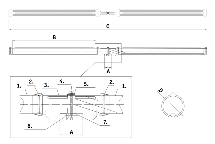
- Membrane
- Clamp
- Diffuser body
- CLIPIN® Bolt
- Washer + Gasket
- CLIPIN® locking latch
- Gasket
| MAGNUM® tube diffusers for stainless steel rectangular laterals | ||||||
|---|---|---|---|---|---|---|
| Article designation | A | C Overall length | D | Materia | ||
| MAGNUM® 1000 | MAGNUM® 1500 | MAGNUM® 2000 | ||||
| MAGNUM® on 80 x 80 square | 80 mm / 3.2" | 1200 mm / 47.2" | 1700 mm / 67.0" | 2200 mm / 86.6" | Ø 63 mm / 2.5" | PP |
| MAGNUM® on 100 x 100 square | 100 mm / 3.9" | 1200 mm / 47.2" | 1700 mm / 67.0" | 2200 mm / 86.6" | Ø 63 mm / 2.5" | PP |
| MAGNUM® on 120 x 120 square | 120 mm / 4.7" | 1200 mm / 47.2" | 1700 mm / 67.0" | 2200 mm / 86.6" | Ø 63 mm / 2.5" | PP |
| MAGNUM® on 3" x 3" square | 76,2 mm / 3" | 1200 mm / 47.2" | 1700 mm / 67.0" | 2200 mm / 86.6" | Ø 63 mm / 2.5" | PP |
| MAGNUM® on 4" x 4" square | 101,6/4" | 1200 | 1700 | 2200 | Ø 63 | PP |
| Active membrane surface | - | 0,16 m² / 1.7 ft² | 0,24 m² / 2.6 ft² | 0,32 m² / 3.4 ² | ||
| Active membrane length (mm) 2xB | - | 2 x 500 | 2 x 750 | 2 x 1000 | ||
| Weight /diffuser (kg) | - | 2,0 | 2,3 | 2,7 | ||
| Buoyancy in operation/ diffuser (kg) | - | 1,0 | 1,4 | 1,9 | ||
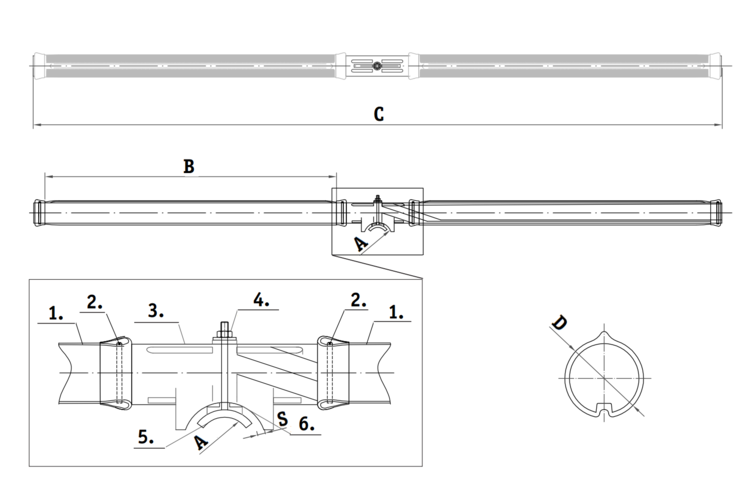
MAGNUM® Tube Diffusers for Stainlesss Steel Round Laterals

- Membrane
- Clamp
- Diffuser body
- CLIPIN® Bolt
- Washer + Gasket
- CLIPIN® locking latch
- Gasket
| MAGNUM® tube diffusers for stainless steel round laterals | ||||||
|---|---|---|---|---|---|---|
| Article designation | A (mm) | C (mm) Overall length | D (mm) | Material | ||
| MAGNUM® 1000 | MAGNUM® 1500 | MAGNUM® 2000 | ||||
| MAGNUM® DN 80 | Ø 88,9 | 1200 | 1700 | 2200 | Ø 63 | PP |
| MAGNUM® DN 100 | Ø 114,3 | 1200 | 1700 | 2200 | Ø 63 | PP |
| MAGNUM® DN 125 | Ø 139,7 | 1200 | 1700 | 2200 | Ø 63 | PP |
| MAGNUM® 3" (OD 3,5) | Ø 88,9/3" | 1200 | 1700 | 2200 | Ø 63 | PP |
| MAGNUM® 4" (OD 4,5) | Ø 114,3/4" | 1200 | 1700 | 2200 | Ø 63 | PP |
| Active membrane surface (m²) | - | 0,16 | 0,24 | 0,32 | ||
| Active membrane length (mm) 2xB | - | 2 x 500 | 2 x 750 | 2 x 1000 | ||
| Weight/diffuser (kg) | - | 2,0 | 2,3 | 2,7 | ||
| Buoyancy in operation/ diffuser (kg) | - | 1,0 | 1,4 | 1,9 | ||
MAGNUM® Tube Diffusers for Round Polypropylene Laterals
- Membrane
- Clamp
- Diffuser body
- CLIPIN® Bolt + Gasket
- CLIPIN® locking latch
- Gasket
| MAGNUM® tube diffuser for round polypropylene laterals | ||||||
|---|---|---|---|---|---|---|
| Article designation | A (mm) | C (mm) Overall length | D (mm) | Material | ||
| MAGNUM® 1000 | MAGNUM® 1500 | MAGNUM® 2000 | ||||
| MAGNUM® DN 80 | Ø 88,9 | 1200 | 1700 | 2200 | Ø 63 | PP |
| MAGNUM® DN 100 | Ø 114,3 | 1200 | 1700 | 2200 | Ø 63 | PP |
| Active membrane surface (m²) | - | 0,16 | 0,24 | 0,32 | ||
| Active membrane length (mm) 2xB | - | 2 x 500 | 2 x 750 | 2 x 1000 | ||
| Weight / diffuser (kg) | - | 2,0 | 2,3 | 2,7 | ||
| Buoyancy in operation / diffuser (kg) | - | 1,0 | 1,4 | 1,9 | ||
MAGNUM® T Tube Diffusers for Installation on 1″ Male Thread Mounts

| MAGNUM® T tube diffuser for 1″ male thread mounts | ||||||
|---|---|---|---|---|---|---|
| Article designation | A (mm) | C (mm) Overall length | D (mm) | Material | ||
| MAGNUM® 1000 | MAGNUM® 1500 | MAGNUM® 2000 | ||||
| MAGNUM® T | 1" IT | 1200 | 1700 | 2200 | Ø 63 | PP |
| Active membrane surface (m²) | - | 0,16 | 0,24 | 0,32 | ||
| Active membrane length (mm) 2xB | - | 2 x 500 | 2 x 750 | 2 x 1000 | ||
| Weight/diffuser (kg) | - | 2,0 | 2,3 | 2,7 | ||
| Buoyancy in operation/ diffuser (kg) | - | 1,0 | 1,4 | 1,9 | ||
MAGNUM® Tube Diffusers for AirRex® Laterals

- Membrane
- Clamp
- Diffuser body
- Diffuser cap + Gasket
| MAGNUM® tube diffuser for AirRex® lateral | ||||||
|---|---|---|---|---|---|---|
| Article designation | A (mm) | C (mm) Overall length | D (mm) | Material | ||
| MAGNUM® 1000 | MAGNUM® 1500 | MAGNUM® 2000 | ||||
| MAGNUM® for AirRex® | R 57,15 | 1200 | 1700 | 2200 | Ø 63 | PP |
| Active membrane surface (m²) | - | 0,16 | 0,24 | 0,32 | ||
| Active membrane length (mm) 2xB | - | 2 x 500 | 2 x 750 | 2 x 1000 | ||
| Weight/diffuser (kg) | - | 2,0 | 2,3 | 2,7 | ||
| Buoyoncy in operation / diffuser (kg) | - | 1,0 | 1,4 | 1,9 | ||
Diffuser Securing Nut for MAGNUM® AirRex

| Diffuser securing nut | |||||||
|---|---|---|---|---|---|---|---|
| Article designation | Article number | A (mm) | B (mm) | C (mm) | D (mm) | E (mm) | F (mm) |
| Diffuser securing nut | 4190000000 | Ø 50 | 46 | Ø 36 | Ø 28 | Ø 28 (G ¾") | 8 |
| Material | PP–GF | ||||||
| Weight | ~30g | ||||||
Gaskets

- Gasket (large)
- Gasket (small)
| Gaskets | |||||||||
|---|---|---|---|---|---|---|---|---|---|
| Article designation | Article number | A (mm) | B (mm) | C (mm) | D (mm) | E (mm) | F (mm) | G (mm) | Material |
| Dichtungssatz | 4130000000 | Ø 50 | 5 | 7,5 | 7 | Ø 15 | Ø 9 | 7 | TPE |
Mounting Hardware For Dummy Plug (On Rectangular Laterals)
- Washer
- Locking latch
- Bolt
- Dummy plug
- Gasket (large)
- Gasket (small)
| Mounting hardware for dummy plug (on rectangular laterals) | ||||||||||||
|---|---|---|---|---|---|---|---|---|---|---|---|---|
| Article designation | Article number | A (mm) | B (mm) | C (mm) | D (mm) | E (mm) | F (mm) | G (mm) | H (mm) | I (mm) | J (mm) | Material |
| Dummy plug | 4120020000 | 22,69 | 39,03 | 15 | Ø 58 | Ø 50,8 | Ø 32 | 8,2 | Ø 16 | Ø 40,5 | Ø 50,8 | PP |
| Gasket | 4130000000 | Ø 50 | 5 | Ø 7,5 | 7 | Ø 15 | Ø 9 | 7 | - | - | - | TPE |
| Bolt | as set: 4111004001 | 50 | 28 | M8 | 8 | Ø13 | IMB 6 | - | - | - | - | V4A |
| Locking latch | as set: 4111004001 | 50 | 25 | 15 | 8 | M8 | - | - | - | - | - | V2A |
| Washer | as set: 4111004001 | Ø 28 | Ø 9 | 3 | - | - | - | - | - | - | - | V4A |
Dummy Plug Set for Round Laterals
- Washer
- Locking latch
- Bolt
- Dummy plug
- Gasket (large)
- Gasket (large)
| Mounting hardware for dummy plug (on round laterals) | ||||||||||||||
|---|---|---|---|---|---|---|---|---|---|---|---|---|---|---|
| Article designation | Article number | A (mm) | B (mm) | C (mm) | D (mm) | E (mm) | F (mm) | G (mm) | H (mm) | I (mm) | J (mm) | K (mm) | L (mm) | Material |
| Dummy plug DN 80* | 41120008000 | 22,85 | 39,03 | 15 | Ø 58 | Ø 50,8 | Ø 32 | 8,2 | Ø 16 | 40,5 | Ø 50,8 | 26,72 | R40 | PP |
| Gasket set | 4130000000 | Ø 50 | 5 | Ø 7,5 | 7 | Ø 15 | Ø 9 | 7 | - | - | - | - | - | TPE |
| Bolt | as set: 4111004001 | 50 | 28 | M8 | 8 | Ø 13 | IMB6 | - | - | - | - | - | - | V4A |
| Locking latch | as set: 4111004001 | 50 | 25 | 15 | 8 | M8 | - | - | - | - | - | - | - | V4A |
| Washer | as set: 4111004001 | Ø 28 | Ø 9 | 3 | - | - | - | - | - | - | - | - | - | V4A |
CLIPIN® Mounting Hardware for Rectangular Laterals
- Locking bolt
- Locking latch
- Washer
- Set
- Gasket (large)
- Gasket (small)
| CLIPIN® mounting hardware set for rectangular laterals | |||||||||
|---|---|---|---|---|---|---|---|---|---|
| Article designation | Article number | A (mm) | B (mm) | C (mm) | D (mm) | E (mm) | F (mm) | G (mm) | Available materials |
| Locking bolt | as set: 4111004000 | M8 | 25 | 100 | SW 13 | - | - | - | V4A |
| Locking latch | as set: 4111004000 | 50 | 15 | 8 | M8 | - | - | - | V4A |
| Washer | as set: 4111004000 | Ø 30 | Ø 9 | 3 | - | - | - | - | V4A |
| Gaskets | 4130000000 | Ø 50 | 5 | Ø 7,5 | 7 | Ø 15 | Ø 9 | 7 | TPE |
CLIPIN® Mounting Hardware for Round Plastic Laterals

- Locking latch
- Washer
- Nut
- Set
- Gasket (large)
- Gasket (small)
| CLIPIN® mounting hardware set for round plastic laterals | ||||||||||
|---|---|---|---|---|---|---|---|---|---|---|
| Article designation | A (mm) | B (mm) | C (mm) | D (mm) | E (mm) | F (mm) | G (mm) | H (mm) | I (mm) | Available materials |
| Locking latch for DN 125 PP pipe | 55 | 50 | R 54 | 8 | 100 | 40 | M8 | R21,25 | 20 | HCR/V2A/V4A |
| Locking latch for DN 100 PP pipe | 55 | 49 | R 49 | 8 | 100 | 40 | M8 | R21,25 | 20 | HCR/V2A/V4A |
| Locking latch for DN 80 PP pipe | 55 | 46 | R 37 | 8 | 100 | 40 | M8 | R21,25 | 20 | HCR/V2A/V4A |
| M8 Nut | 14,38 | 6,5 | M8 | SW13 | - | - | - | - | - | HCR/V2A/V4A |
| Washer | Ø 30 | Ø 9 | 3 | - | - | - | - | - | - | HCR/V2A/V4A |
| Gasket | Ø 50 | 5 | Ø 7,5 | 7 | Ø 15 | Ø 9 | 7 | - | - | TPE |
Diffuser Mounting Connector for MAGNUM® AirRex

| Diffuser mounting connector | |||||
|---|---|---|---|---|---|
| Article designation | Article number | A (mm) | B (mm) | C (mm) | D (mm) |
| Diffuser mounting connector | 4199000000 | 102 | Ø 35,5 | G ¾"(BSP) | G ¾"(BSP) |
| Material | PP–GF | ||||
| Weight | ~50 g | ||||
Guard Cap
- Front view
- Rear view
- Side view
| Guard cap | |||||||
|---|---|---|---|---|---|---|---|
| Article designation | Article number | A | B | C | D | E | Material |
| Guard cap | 4121000000 | 62 mm / 2.4" | 31 mm / 1.2" | 8 mm / 0.3" | 10 mm / 0.4" | 54 mm / 2.1" | PP |
| Incl. mounting set: hex head screw 8x25, DIN 933, hex nut M8, DIN 934 | |||||||
Guard Rails
| Guard rails | ||||||||||||
|---|---|---|---|---|---|---|---|---|---|---|---|---|
| Article designation | Article number | Number of drill holes | A | B | C | D | E | F | G | H | I | J |
| Guard rail AirRex® | 4121000001 | 6 | 17 mm / 0.7" | 13 mm / 0.5" | 200 mm / 7.9" | 1200 mm / 47.2" | Ø 13 mm / 0.5" | 50 mm / 2" | 300 mm / 11.8" | 1600 mm / 63" | 4 mm / 0.2" | 30 mm / 1.2" |
| Guard rail AirRex+® | 4121000002 | 8 | 17 mm / 0.7" | 13 mm / 0.5" | 200 mm / 7.9" | 1205 mm / 47.4" | Ø 13 mm / 0.5" | 50 mm / 2" | 215 mm / 8.5" | 1605 mm / 63.2" | 4 mm / 0.2" | 30 mm / 1.2" |
| Guard rail custom | 4121000003 | * | 17 mm / 0.7" | 13 mm / 0.5" | 200 mm / 7.9" | * | Ø 13 mm / 0.5" | * | * | * | 4 mm / 0.2" | 30 mm / 1.2" |
| * depending on coordination / drawing | ||||||||||||
D-REX®
D-REX® Disc Diffusers

| D-REX® disc diffuser | |||||||
|---|---|---|---|---|---|---|---|
| Article designation | Membrane | Article number | A Outer diameter (mm) | B Membrane surface (mm/m²) | C Height (mm) | D Connecting thread (“) | Weight |
| D-REX® disc diffuser | FLEXLON® | 9942700002 | 276 | Ø 265 A=0,055m² | 46 | ¾” BSP internal | ~ 736g |
| Dimensions and specifications component | 2 Diffuser body | 3 Support ring |
| Material | PP-GF | PP-GF |
| Weight | 350 g | 156 g |
D-REX® ¾″ CLIPIN® Adapter for Rectangular Laterals

- ¾″ CLIPIN® Adapter D-REX® for Rectangular Laterals
- Locking latch
- Bolt
- Gasket
- Front view
- Rear view
- Side view
| D-REX® ¾″ CLIPIN® Adapter for Rectangular Laterals | ||||||||
|---|---|---|---|---|---|---|---|---|
| Article designation | Article number | A (mm) | B (mm) | C (mm) | D (mm) | E (mm) | F (mm) | Material |
| D-REX® ¾″ CLIPIN® Adapter for Rectangular Laterals for 30mm borehole | 4111001400 | 26,44 (¾”) | Ø 31 | 46 | 17,5 | - | - | PP-GF |
| Bolt | as set: 4111004001 | 50 | 28 | M8 | 8 | Ø 13 | IMB 6 | V4A |
| Locking latch | as set: 4111004001 | 50 | 25 | 15 | 8 | M8 | - | V4A |
| Washer | as set: 4111004001 | Ø 28 | Ø 9 | 3 | - | - | - | V4A |
| Gasket | as set: 4111004001 | Ø 36 | Ø 31 | 3 | - | - | - | EPDM |
Instruction for installation:
Screw down the nut (Inbus 6) of the adapter with a torque of 20Nm!
Please note:
Don’t use any grease or oil for installation, be certain that all components are dry when installed.
D-REX® ¾″ CLIPIN® Adapter for Round Laterals

- ¾″ CLIPIN® Adapter D-REX® for Round Laterals
- Locking latch
- Bolt
- Gasket
- Front view
- Rear view
- Side view
| D-REX® ¾″ CLIPIN® Adapter for Round Laterals | |||||||||
|---|---|---|---|---|---|---|---|---|---|
| Article designation | Article number | A (mm) | B (mm) | C (mm) | D (mm) | E (mm) | F (mm) | Material | |
| D-REX® ¾″ CLIPIN® Adapter for Round Laterals DN80 for 30mm borehole | 4111001401 | 26,44 (¾”) | Ø 31 | 46 | 17,5 | Ø 88,9 | - | PP-GF | |
| D-REX® ¾″ CLIPIN® Adapter for Round Laterals 90 mm for 30mm borehole | 4111001404 | 26,44 (¾”) | Ø 31 | 46 | 17,5 | Ø 90 | - | PP-GF | |
| D-REX® ¾″ CLIPIN® Adapter for Round Laterals DN100 for 30mm borehole | 4111001402 | 26,44 (¾”) | Ø 31 | 46 | 17,5 | Ø 114,3 | - | PP-GF | |
| D-REX® ¾″ CLIPIN® Adapter for Round Laterals 110 mm for 30mm borehole | 4111001405 | 26,44 (¾”) | Ø 31 | 46 | 17,5 | Ø 110 | - | PP-GF | |
| Bolt | as set: 4111004001 | 50 | 28 | M8 | 8 | Ø 13 | IMB 6 | V4A | |
| Locking latch | as set: 4111004001 | 50 | 25 | 15 | 8 | M8 | - | V4A | |
| Washer | as set: 4111004001 | Ø 28 | Ø 9 | 3 | - | - | - | V4A | |
| Gasket | as set: 4111004001 | Ø 36 | Ø 31 | 3 | - | - | - | EPDM | |
Instruction for installation:
Screw down the nut (Inbus 6) of the adapter with a torque of 20Nm!
Please note:
Don’t use any grease or oil for installation, be certain that all components are dry when installed.
D-REX® Double Nipple

| D-REX® double nipple | |||||||
|---|---|---|---|---|---|---|---|
| Article designation | Article number | A (mm) | B (mm) | C (mm) | D (mm) | E (mm) | F (mm) |
| D-REX® double nipple | 4420482001 | 58 | 26,5 | 5 | 26,5 | Ø ¾” (BSP) | Ø ¾” (BSP) |
| D-REX® double nipple NPT | 4429482001 | 58 | 26,5 | 5 | 26,5 | Ø ¾” (BSP) | Ø ¾” NPT |
| Material | PP-GF | ||||||
| Weight | ~20 g | ||||||
Saddle Adapters D-REX®

| Saddle Adapters D-REX® | |||||||
|---|---|---|---|---|---|---|---|
| Article designation | Article number | A (mm) | B (mm) | C (mm) | D (mm) | E Thread | Material |
| DN 80 round header / 20 mm hole | 4220001080 | 164,3 | 88,9 | 12 | 136 | ¾″ BSP | PP-GF |
| DN 80 round header / 40 mm hole | 4330001080 | 164,3 | 88,9 | 12 | 136 | ¾″ BSP | PP-GF |
| DN 80 round header / 45 mm hole | 4450001080 | 164,3 | 88,9 | 12 | 136 | ¾″ BSP | PP-GF |
| 90 mm round header / 20 mm hole | 4220001090 | 164,3 | 90 | 12 | 136 | ¾″ BSP | PP-GF |
| 90 mm round header / 40 mm hole | 4330001090 | 164,3 | 90 | 12 | 136 | ¾″ BSP | PP-GF |
| 90 mm round header / 45 mm hole | 4450001090 | 164,3 | 90 | 12 | 136 | ¾″ BSP | PP-GF |
| 110 mm round header / 20 mm hole | 4220001110 | 194,3 | 110 | 12 | 166 | ¾" BSP | PP-GF |
| 110 mm round header / 40 mm hole | 4330001110 | 194,3 | 110 | 12 | 166 | ¾" BSP | PP-GF |
| 110 mm round header / 45 mm hole | 4450001110 | 194,3 | 110 | 12 | 166 | ¾" BSP | PP-GF |
| DN 100 round header / 20 mm hole | 4220001100 | 194,3 | 114,3 | 12 | 166 | ¾" BSP | PP-GF |
| DN 100 round header / 40 mm hole | 4330001100 | 194,3 | 114,3 | 12 | 166 | ¾" BSP | PP-GF |
| DN 100 round header / 45 mm hole | 4450001100 | 194,3 | 114,3 | 12 | 166 | ¾" BSP | PP-GF |
| DN 125 round header / 20 mm hole | 4220001125 | 212,5 | 139,7 | 12 | 186 | ¾" BSP | PP-GF |
| DN 125 round header / 40 mm hole | 4330001125 | 212,5 | 139,7 | 12 | 186 | ¾" BSP | PP-GF |
| DN 125 round header / 45 mm hole | 4450001125 | 212,5 | 139,7 | 12 | 186 | ¾" BSP | PP-GF |
| 140 mm round header / 20 mm hole | 4220001140 | 212,5 | 139,7 | 12 | 186 | ¾" BSP | PP-GF |
| 140 mm round header / 40 mm hole | 4330001140 | 212,5 | 139,7 | 12 | 186 | ¾" BSP | PP-GF |
| 140 mm round header / 45 mm hole | 4450001140 | 212,5 | 139,7 | 12 | 186 | ¾" BSP | PP-GF |
Saddle Adapter Seals
| Saddle Adapter Seals | ||||||||
|---|---|---|---|---|---|---|---|---|
| Article designation | Article number | A | B | C | Material | Article | ||
| Inner seal | 4242220004 | 55 mm / 2.2" | 50 mm / 2" | 3,5 mm / 0.1" | EPDM | 2. | ||
| Outer seal | 4242200004 | 60 mm / 2.4" | 34,5 mm / 14" | 3 mm / 0.1" | EPDM | 3. | ||
Mounting Hardware for Saddle Adapter
| Mounting Hardware for Saddle Adapter | ||||||||
|---|---|---|---|---|---|---|---|---|
| Article designation | Article number | A | B | C | D | Material | Artikel | |
| Bolt | - | M8 | 35 mm / 1.4" | IMB 6 | - | V4A | 4. | |
| Nut plate | - | 50 mm / 2" | 15 mm / 0.6" | 5 mm / 0.2" | M8 | V4A | 5. | |
| Plate washer | - | 50 mm / 2" | 15 mm / 0.6" | 5 mm / 0.2" | Ø 9 mm / 0.4" | V4A | 6. | |
AirRex®
AirRex® Modules

| AirRex® modules | |||||||
|---|---|---|---|---|---|---|---|
| Article designation | Article number | A | B | C | D | E | F |
| AirRex® module | 9211000000 | 1875mm / 73.82" | Ø 114,3 / 45" | 155mm / 6.10" | 180mm / 7.09" | 300mm / 11.81" | Ø ¾” IT BSP |
| Material | PP–GF | ||||||
| Weight | ~4,7 kg | ||||||
AirRex®+ Modules

| AirRex®+ modules | |||||||
|---|---|---|---|---|---|---|---|
| Article designation | Article number | A (mm) | B (mm) | C (mm) | D (mm) | E (mm) | F (mm) |
| AirRex®+ module | 9800000000 | 1875mm / 73.82" | Ø 114,3 / 45" | 155mm / 6.10" | 180mm / 7.09" | 215 / 8.46" | Ø ¾” IT BSP |
| Material | PP–GF | ||||||
| Weight | ~4,7 kg | ||||||
AirRex® Adapter for Pipe Socket

| AirRex® Adapter for Pipe Socket | ||||||
|---|---|---|---|---|---|---|
| Article designation | Article number | A | B | C | D | E |
| AirRex® adapter DN 50 | 9091112000 | 140mm / 5.51" | 168mm / 6.61" | 60,3mm / 23.74" | 61mm / 2.40" | Ø 125,7mm / 49.49" |
| AirRex® adapter DN 65 | 9091120000 | 140mm / 5.51" | 168mm / 6.61" | 76,1mm / 29.96" | 61mm / 2.40" | Ø 125,7mm / 49.49" |
| AirRex® adapter DN 80 | 9091122000 | 168mm / 6.61" | 168mm / 6.61" | 88,9mm / 35" | 61mm / 2.40" | Ø 125,7mm / 49.49" |
| AirRex® adapter DN 100 | 9091000000 | 140mm / 5.51" | 168mm / 6.61" | 114,3mm / 45" | 61mm / 2.40" | Ø 125,7mm / 49.49" |
| Material | PP–GF | |||||
| Weight | ~300g | |||||
AirRex® Adapter for Round Header with Drill Hole

| AirRex® Adapter for Round Header with Drill Hole | ||||||
|---|---|---|---|---|---|---|
| Article designation | Article number | A | B | C | D | E |
| AirRex® Adapter DN 125 | 9029111125 | 212,1mm / 83.5" | Ø 139,7mm / 55" | 204,87mm / 806.57" | 186mm / 7.32" | Ø 113mm / 4.45" |
| AirRex® Adapter 140 mm | 9029111140 | 212,1mm / 83.5" | Ø 139,7mm / 55" | 204,87mm / 806.57" | 186mm / 7.32" | Ø 113mm / 4.45" |
| AirRex® Adapter DN 150 | 9029111150 | 244,7mm / 96.34" | Ø 168,3mm / 66.26" | 218,7mm / 86.10" | 216mm / 8.50" | Ø 113mm / 4.45" |
| AirRex® Adapter 180 mm | 9029111180 | 246,5mm / 97.05" | Ø 180mm / 7.09" | 230,37mm / 906.97" | 216mm / 8.50" | Ø 113mm / 4.45" |
| Material | PP-GF | |||||
| Weight | ~500g | |||||
AirRex® End Cap

| AirRex® end cap | ||||||
|---|---|---|---|---|---|---|
| Article designation | Article number | A | B | C | D | E |
| AirRex® end cap | 9911100000 | 151mm / 5.95 | 168mm / 6.61" | 114,5mm / 45" | 30mm / 1.18" | 26,4mm / 10.40" |
| Material | PP–GF | |||||
| Weight | ~300g | |||||
AirRex® Mounting Clamp

| AirRex® mounting clamp | |||||||
|---|---|---|---|---|---|---|---|
| Article designation | Article number | A | B | C | D | E | F |
| AirRex® mounting clamp | 9011000014 | 220mm / 8.66" | 200mm / 7.87" | 50mm / 1.97" | Ø 11,5mm / 4.53 | R 56,8mm / R 22.36" | 67mm / 2.64" |
| Material | PP–GF | ||||||
| Weight | 270 g | ||||||
AirRex® dummy plug

| AirRex® dummy plug | |||||
|---|---|---|---|---|---|
| Article designation | Article number | A | B | C | D |
| AirRex® dummy plug | 9011000013 | SW 20mm / SW 0.79" | SW 36mm / SW 1.42" | ¾” (BSP) | 35,5mm / 13.98" |
| Material | PP–GF | ||||
| Weight | ~25 g | ||||
AirRex® Gaskets
- Front view
- Rear view
- Side view
| Gasket for AirRex® | |||||
|---|---|---|---|---|---|
| Article designation | Article number | A | B | C | Material |
| Gasket AirRex® blue | 9011000003 | Ø 116mm / 4.57" | Ø 109mm / 4.29" | 4,5mm / 1.77" | TPE |
| Gasket AirRex® red | 9011000008 | Ø 116mm / 4.57" | Ø 109mm / 4.29" | 4,5mm / 1.77" | TPE |
Flexible Transisition Hose

| AirRex® flexible transition hose | ||||
|---|---|---|---|---|
| Article designation | Article number | A | B | C |
| AirRex® flexible transition hose DN 50 | 9011002222 | 150mm / 5.91" | Ø 70,3mm / 27.68" | Ø 60,3mm / 23.74" |
| AirRex® flexible transition hose DN 65 | 9011000222 | 150mm / 5.91" | Ø 86,1mm / 33.90" | Ø 76,1mm / 29.96" |
| AirRex® flexible transition hose DN 80 | 9011000022 | 150mm / 5.91" | Ø 98,9mm / 38.94" | Ø 88,9mm / 35" |
| AirRex® flexible transition hose DN 100 | 9011000002 | 150mm / 5.91" | Ø 124,3mm / 48.94" | Ø 114,3mm / 45" |
| Material | Silicone | |||
| Weight | ~300 g | |||
Anchor Rods Set

- Anchor Rods Set 250 mm 250 mm / 9.84"
- Anchor Rods Set 330 mm 330 mm / 12.99"
- Anchor Rods Set 500 mm / 19.69"
- Nuts M10
- Washers M10
- Anchor rods M10
- Chemical anchor cartridges
- Flat steel bracket
| Anchor Rods Set | |||
|---|---|---|---|
| Article designation | Article number | Length | Material |
| Anchor Rods Set 250 mm 1.4571/SS316 | 9650000250 | 250 mm / 9.84" | V4A |
| Anchor Rods Set 330 mm 1.4571/SS316 | 9650000330 | 330 mm / 12.99" | V4A |
| Anchor Rods Set 500 mm 1.4571/SS316 | 9650000500 | 500 mm / 19.69" | V4A |
| Anchor Rods Set 250 mm HCR 1.4529 | 9651000250 | 250 mm / 9.84" | HCR |
| Anchor Rods Set 330 mm HCR 1.4529 | 9651000330 | 330 mm / 12.99" | HCR |
| Anchor Rods Set 500 mm HCR 1.4529 | 9651000500 | 500 mm / 19.69" | HCR |
| Fastening set for one clamp consisting of: 2 anchor rods M10, 2 chemical anchor cartridges, 4 Washers M10, 4 Nuts M10 | |||

- Anchor rod
- Washer
- Nut
- Chemical anchor cartridge
| - | A | B | C | D | No. |
|---|---|---|---|---|---|
| Nut M10 | 18,9mm / 7.44" | 8 mm / 0.31" | M10 | SW 17 mm / 0.67" | 3. |
| Washer | Ø 20mm / 0.79" | Ø 10,5mm / 4.13" | 2mm / 0.8" | - | 2. |
| Anchor rod | M10 | 250mm/9.84" 330mm/12.99" 500mm/19.69" | - | - | 1. |
| Chemical anchor cartridge | Ø 10mm / 0.39" | 90mm / 3.54" | - | - | 4. |
FLEXNORM® Tubular Membranes For 63 mm O.D. Diffuser Bodies
Material specification
FLEXNORM® is an ethylene propylene diene monomer (EPDM) elastomer
| Colour | Black |
| Shore hardness DIN 53505 | A 45 +/-5 |
| Maximum service temperature | 80 °C |
| Tear propagation resistance ISO 34-1 A | ≥ 10 N/mm |
Dimensions

| Dimensions / FLEXNORM® tubular membranes | |||||||
|---|---|---|---|---|---|---|---|
| Article designation | Article number | A Active membrane length | B Overall length | D Inner diameter | Active membrane surface | Material | Colour |
| MB FLEXNORM® 460 | 3400460000 | 460mm / 18.11" | 520mm / 20.47" | Ø 65,0mm - 66,0mm / 2.56" - 2.60" | 0,08m² / 86.11ft² | EPDM | black |
| MB FLEXNORM® 500 | 3400500000 | 500mm / 19.69" | 560mm / 22.05" | Ø 65,0mm - 66,0mm / 2.56" - 2.60" | 0,08m² / 86.11ft² | EPDM | black |
| MB FLEXNORM® 542 | 3400542000 | 542mm / 21.34" | 602mm / 23.70" | Ø 65,0mm - 66,0mm / 2.56" - 2.60" | 0,09m² / 96.88"ft² | EPDM | black |
| MB FLEXNORM® 720 | 3400650000 | 720mm / 28.35" | 780mm / 30.71" | Ø 65,0mm - 66,0mm / 2.56" - 2.60" | 0,11m² / 118.4"ft² | EPDM | black |
| MB FLEXNORM® 750 | 3400750000 | 750 | 810 | Ø 65,0 - 66,0 | 0,12 | EPDM | black |
| MB FLEXNORM® 770 | 3400770000 | 770 | 830 | Ø 65,0 - 66,0 | 0,12 | EPDM | black |
| MB FLEXNORM® 875 | 3400875000 | 875 | 935 | Ø 65,0 - 66,0 | 0,14 | EPDM | black |
| MB FLEXNORM® 950 | 3401000001 | 950 | 1010 | Ø 65,0 - 66,0 | 0,16 | EPDM | black |
| MB FLEXNORM® 1000 | 3401000000 | 1000 | 1060 | Ø 65,0 - 66,0 | 0,16 | EPDM | black |
| MB FLEXNORM® 1109 | 3401109000 | 1109 | 1169 | Ø 65,0 - 66,0 | 0,18 | EPDM | black |
| MB FLEXNORM® 1146 | 3401146000 | 1146 | 1206 | Ø 65,0 - 66,0 | 0,19 | EPDM | black |
| MB FLEXNORM® 1300 | 3401300000 | 1300 | 1360 | Ø 65,0 - 66,0 | 0,20 | EPDM | black |
| MB FLEXNORM® 1920 | 3401108000 | 1920 | 1980 | Ø 65,0 - 66,0 | 0,35 | EPDM | black |
Slit pattern and slit size
The tubular membrane is perforated by a specially configured pattern of slits. It has no perforation at its 6 o’clock and 12 o’clock positions as well as on both ends. The slit size is dimensioned in accordance with the specific diffuser type and application at hand. Slit sizes are available in the following range: 0.6 / 1.0 / 1.2 / 1.4 / 2.0 mm.
Pressure drop vs. throughput for FLEXNORM® membranes in new condition with different perforation grades
The diagram above is a plot of maximum diffuser pressure drop (i.e. the pressure drop used for blower dimensioning) as a function of air throughput for different perforation grades. The pressure drop data applies for diffusers and membranes in new condition. The actual pressure drops across new diffusers/membranes will be lower and can vary in a given delivery lot within a window of 6 mbar (0.09 psi).
For example, a 1.4 mm thick FLEXNORM® membrane used at an air throughput of 15 m³/h will have:
a maximum pressure drop (i.e. the pressure drop used in blower dimensioning) of: 60 mbar (0.87 psi) and a pressure drop window within the lot of e.g.: 50 – 56 mbar (0.72 – 0.81 psi).
The pressure drop across a diffuser or membrane can change in subsequent operation. The amount of change depends on the purity of the inlet air, composition of the wastewater treated, process chemicals used and their concentrations as well as the aeration process technology and process conditions.
Due to these many variable factors, we cannot specify the increase in pressure drop to be expected in actual operation in your WWTP. We will however gladly advise you in accordance with our experience and develop, using your input parameters, operating conditions and maintenance plans which reduce pressure drop build-up.
FLEXNORM® Tubular Membranes For 90 mm O.D. Diffuser Bodies
Material specification
FLEXNORM® is an ethylene propylene diene monomer (EPDM) elastomer
| Colour | Black |
| Shore hardness DIN 53505 | A 45 +/-5 |
| Maximum service temperature | 80 °C |
| Tear propagation resistance ISO 34-1 A | ≥ 10 N/mm |
Dimensions
| Dimensions / FLEXNORM® tubular membranes | |||||||
|---|---|---|---|---|---|---|---|
| Article designation | Article number | A (mm) Active membrane length | B (mm) Overall length | D (mm) Inner diameter | Material | Colour | |
| MB FLEXNORM® 1000 90mm | 3401000090 | 1000 | 1060 | Ø 92.5 | EPDM | black | |
Slit pattern and slit size
The tubular membrane is perforated by a specially configured pattern of slits. It has no perforation at its 6 o’clock and 12 o’clock positions as well as on both ends. The slit size is dimensioned in accordance with the specific diffuser type and application at hand. Slit sizes are available in the following range: 0.6 / 1.0 / 1.2 / 1.4 / 2.0 mm.
Pressure drop vs. throughput for FLEXNORM® membranes in new condition with different perforation grades
The diagram above is a plot of maximum diffuser pressure drop (i.e. the pressure drop used for blower dimensioning) as a function of air throughput for different perforation grades. The pressure drop data applies for diffusers and membranes in new condition. The actual pressure drops across new diffusers/membranes will be lower and can vary in a given delivery lot within a window of 6 mbar (0.09 psi).
For example, a 1.4 mm thick FLEXNORM® membrane used at an air throughput of 15 m³/h will have:
a maximum pressure drop (i.e. the pressure drop used in blower dimensioning) of: 60 mbar (0.87 psi) and a pressure drop window within the lot of e.g.: 50 – 56 mbar (0.72 – 0.81 psi).
The pressure drop across a diffuser or membrane can change in subsequent operation. The amount of change depends on the purity of the inlet air, composition of the wastewater treated, process chemicals used and their concentrations as well as the aeration process technology and process conditions.
Due to these many variable factors, we cannot specify the increase in pressure drop to be expected in actual operation in your WWTP. We will however gladly advise you in accordance with our experience and develop, using your input parameters, operating conditions and maintenance plans which reduce pressure drop build-up.
FLEXSIL® Tubular Membranes For OTT Diffuser Bodies with Retaining Ridge
Material specification
FLEXSIL® is a polyorganosiloxane elastomer (silicone elastomer)
| Colour | white-grey |
| Shore hardness DIN 53505 | A 60 +/- 5 |
| Maximum service temperature | 140 °C |
| Tear propagation resistance ISO 34-1 B | > 35 N/mm |
Dimensions
| Dimensions / FLEXSIL® tubular membranes | |||||||
|---|---|---|---|---|---|---|---|
| Article designation | Article number | A (mm) Aktive membrane length | B (mm) Overall length | D (mm) Inner diameter | Active membrane surface (m²) | Material | Colour |
| MB FLEXSIL® 500 | 3110500000 | 500 | 560 | Ø 65,0 - 65,6 | 0,08 | FLEXSIL® | white-grey |
| MB FLEXSIL® 750 | 3110750000 | 750 | 810 | Ø 65,0 - 65,6 | 0,12 | FLEXSIL® | white-grey |
| MB FLEXSIL® 960 | 3111000960 | 960 | 1020 | Ø 65,0 - 65,6 | 0,18 | FLEXSIL® | white-grey |
| MB FLEXSIL® 1000 | 3111000000 | 1000 | 1060 | Ø 65,0 - 65,6 | 0,16 | FLEXSIL® | white-grey |
Slit pattern and slit size
The tubular membrane is perforated by a specially configured pattern of slits. It has no perforation at its 6 o’clock and 12 o’clock positions as well as on both ends. The slit size is dimensioned in accordance with the specific diffuser type and application at hand. Slit sizes are available in the following range: 0.6 / 1.0 / 1.2 / 1.4 / 2.0 mm.
Pressure drop vs. throughput for OTT FLEXSIL® membranes in new condition with different perforation grades
The diagram above is a plot of maximum diffuser pressure drop (i.e. the pressure drop used for blower dimensioning) as a function of air throughput for different perforation grades. The pressure drop data applies for diffusers and membranes in new condition. The actual pressure drops across new diffusers/membranes will be lower and can vary in a given delivery lot within a window of 6 mbar (0.09 psi).
For example, a 1.0 mm thick FLEXSIL® membrane used at an air throughput of 10 m³/h will have:
a maximum pressure drop (i.e. the pressure drop used in blower dimensioning) of: 60 mbar (0.87 psi) and a pressure drop window within the lot of e.g.: 50 – 56 mbar (0.72 – 0.81 psi).
The pressure drop across a diffuser or membrane can change in subsequent operation. The amount of change depends on the purity of the inlet air, composition of the wastewater treated, process chemicals used and their concentrations as well as the aeration process technology and process conditions.
Due to these many variable factors, we cannot specify the increase in pressure drop to be expected in actual operation in your WWTP. We will however gladly advise you in accordance with our experience and develop, using your input parameters, operating conditions and maintenance plans which reduce pressure drop build-up.
FLEXSIL®+ Tubular Membranes For OTT Diffuser Bodies with Retaining Ridge
Material specification
FLEXSIL+® is a polyorganosiloxane elastomer (silicone elastomer)
| Colour | blue |
| Shore hardness DIN 53505 | A 53 (+8/- 3) |
| Maximum service temperature | 140 °C |
| Tear propagation resistance ISO 34-1 B | > 35 N/mm |
Dimensions
| Dimensions / FLEXSIL® tubular membranes | |||||||
|---|---|---|---|---|---|---|---|
| Article designation | Article number | A (mm) Active membrane length | B (mm) Overall length | D (mm) Inner diameter | Active membrane surface (m²) | Material | Colour |
| MB FLEXSIL+® 500 | 3180500000 | 500 | 560 | Ø 65,0 - 65,6 | 0,08 | FLEXSIL+® | blue |
| MB FLEXSIL+® 750 | 3180750000 | 750 | 810 | Ø 65,0 - 65,6 | 0,12 | FLEXSIL+® | blue |
| MB FLEXSIL+® 1000 | 3181000000 | 1000 | 1060 | Ø 65,0 - 65,6 | 0,16 | FLEXSIL+® | blue |
Slit pattern and slit size
The tubular membrane is perforated by a specially configured pattern of slits. It has no perforation at its 6 o’clock and 12 o’clock positions as well as on both ends. The slit size is dimensioned in accordance with the specific diffuser type and application at hand. Slit sizes are available in the following range: 0.6 / 1.0 / 1.2 / 1.4 / 2.0 mm.
Pressure drop vs. throughput for OTT FLEXSIL+® membranes in new condition with different perforation grades
The diagram above is a plot of maximum diffuser pressure drop (i.e. the pressure drop used for blower dimensioning) as a function of air throughput for different perforation grades. The pressure drop data applies for diffusers and membranes in new condition. The actual pressure drops across new diffusers/membranes will be lower and can vary in a given delivery lot within a window of 6 mbar (0.09 psi).
For example, a 1.0 mm thick FLEXSIL+® membrane used at an air throughput of 10 m³/h will have:
a maximum pressure drop (i.e. the pressure drop used in blower dimensioning) of: 60 mbar (0.87 psi) and a pressure drop window within the lot of e.g.: 50 – 56 mbar (0.72 – 0.81 psi).
The pressure drop across a diffuser or membrane can change in subsequent operation. The amount of change depends on the purity of the inlet air, composition of the wastewater treated, process chemicals used and their concentrations as well as the aeration process technology and process conditions.
Due to these many variable factors, we cannot specify the increase in pressure drop to be expected in actual operation in your WWTP. We will however gladly advise you in accordance with our experience and develop, using your input parameters, operating conditions and maintenance plans which reduce pressure drop build-up.
FLEXSIL® RD Tubular Membranes For 63mm O.D. Smooth Diffuser Bodies
Material specification
FLEXSIL® is a polyorganosiloxane elastomer (silicone elastomer)
| Colour | white-grey |
| Shore hardness DIN 53505 | A 60 +/- 5 |
| Maximum service temperature | 140 °C |
| Tear propagation resistance ISO 34-1 B | > 35 N/mm |
Dimensions
| Dimensions / FLEXSIL® tubular membranes | |||||||
|---|---|---|---|---|---|---|---|
| Article designation | Article number | A (mm) Active membrane length | B (mm) Overall length | D (mm) Inner diameter | Active membrane surface (m²) | Material | Colour |
| MB FLEXSIL® RD 500 | 3120500000 | 500 | 560 | Ø 65,0 - 65,6 | 0,08 | FLEXSIL® | white-grey |
| MB FLEXSIL® RD 750 | 3120750000 | 750 | 810 | Ø 65,0 - 65,6 | 0,12 | FLEXSIL® | white-grey |
| MB FLEXSIL® RD 589 T | 3111000589 | 589 | 675 | Ø 65,0 - 65,6 | 0,19 | FLEXSIL® | white-grey |
| MB FLEXSIL® RD1000 | 3121000000 | 1000 | 1060 | Ø 65,0 - 65,6 | 0,16 | FLEXSIL® | white-grey |
| MB FLEXSIL® RD 780 T | 3111000780 | 780 | 850 | Ø 65,0 - 65,6 | 0,16 | FLEXSIL® | white-grey |
| MB FLEXSIL® RD 1169 T | 3111001170 | 1169 | 1255 | Ø 65,0 - 65,6 | 0,21 | FLEXSIL® | white-grey |
| MB FLEXSIL® RD 1224 T | 3111001310 | 1224 | 1310 | Ø 65,0 - 65,6 | 0,21 | FLEXSIL® | white-grey |
Slit pattern and slit size
The tubular membrane is perforated by a specially configured pattern of slits. It has no perforation at its 6 o’clock and 12 o’clock positions as well as on both ends. The slit size is dimensioned in accordance with the specific diffuser type and application at hand. Slit sizes are available in the following range: 0.6 / 1.0 / 1.2 / 1.4 / 2.0 mm.
Pressure drop vs. throughput for FLEXSIL® membranes in new condition with different perforation grades
The diagram above is a plot of maximum diffuser pressure drop (i.e. the pressure drop used for blower dimensioning) as a function of air throughput for different perforation grades. The pressure drop data applies for diffusers and membranes in new condition. The actual pressure drops across new diffusers/membranes will be lower and can vary in a given delivery lot within a window of 6 mbar (0.09 psi).
For example, a 1.0 mm thick FLEXSIL® membrane used at an air throughput of 10 m³/h will have:
a maximum pressure drop (i.e. the pressure drop used in blower dimensioning) of: 60 mbar (0.87 psi) and a pressure drop window within the lot of e.g.: 50 – 56 mbar (0.72 – 0.81 psi).
The pressure drop across a diffuser or membrane can change in subsequent operation. The amount of change depends on the purity of the inlet air, composition of the wastewater treated, process chemicals used and their concentrations as well as the aeration process technology and process conditions.
Due to these many variable factors, we cannot specify the increase in pressure drop to be expected in actual operation in your WWTP. We will however gladly advise you in accordance with our experience and develop, using your input parameters, operating conditions and maintenance plans which reduce pressure drop build-up.
FLEXNORM® Membrane for D-REX® Disc Diffusers

| FLEXNORM® Membrane | ||||||
|---|---|---|---|---|---|---|
| Article designation | Article number | A (mm) Outer diameter | B (mm) Height Membrane | C (mm) Inner diameter | Membrane surface | Weight |
| Material: EPDM | 3344700001 | Ø 276 | 25,6 | Ø 258 | 0,055 m² | ca. 220 g |
| Tear propagation resistance ISO 34-1 A: ≥ 10 N/mm | ||||||
| Shore hardness: A 60 +/-5 | ||||||
| Service temperature range: <= +80°C | ||||||
Pressure drop for FLEXNORM® membranes in new condition
The diagram above is a plot of maximum diffuser pressure drop (i.e. the pressure drop used for blower dimensioning) as a function of air throughput for different perforation grades. The pressure drop data applies for diffusers and membranes in new condition. The actual pressure drops across new diffusers/membranes will be lower and can vary in a given delivery lot within a window of 6 mbar (0.09 psi).
For example, a FLEXNORM® membrane used at an air throughput of 5 m³/h will have:
a maximum pressure drop (i.e. the pressure drop used in blower dimensioning) of: 28 mbar (0.41 psi) and a pressure drop window within the lot of e.g.: 21 – 27 mbar (0.31 – 0.39 psi).
The pressure drop across a diffuser or membrane can change in subsequent operation. The amount of change depends on the purity of the inlet air, composition of the wastewater treated, process chemicals used and their concentrations as well as the aeration process technology and process conditions.
Due to these many variable factors, we cannot specify the increase in pressure drop to be expected in actual operation in your WWTP. We will however gladly advise you in accordance with our experience and develop, using your input parameters, operating conditions and maintenance plans which reduce pressure drop build-up.
FLEXLON® Membrane for D-REX® Disc Diffusers

| FLEXLON® membrane material | ||||||
|---|---|---|---|---|---|---|
| Dimensions and specifications | Article number | A (mm) Outer diameter | B (mm) Membrane height | C (mm) Inner diameter | Membrane surface | Weight |
| Material: FLEXLON® | 3344700001 | Ø 276 | 25,6 | Ø 258 | 0,055 m² | ca. 230 g |
| Tear propagation resistance ISO 34-1 B: ≥ 25 N/mm | ||||||
| Shore hardness: A 57-64 | ||||||
| Service temperature range: up to 110°C (230°F) | ||||||
3.10.2 Pressure drop for FLEXLON® membranes in new condition
The diagram above is a plot of maximum diffuser pressure drop (i.e. the pressure drop used for blower dimensioning) as a function of air throughput for different perforation grades. The pressure drop data applies for diffusers and membranes in new condition. The actual pressure drops across new diffusers/membranes will be lower and can vary in a given delivery lot within a window of 6 mbar (0.09 psi).
For example, a FLEXLON® membrane used at an air throughput of 7 m³/h will have:
a maximum pressure drop (i.e. the pressure drop used in blower dimensioning) of: 28 mbar (0.41 psi) and a pressure drop window within the lot of e.g.: 20 – 26 mbar (0.29 – 0.38 psi).
The pressure drop across a diffuser or membrane can change in subsequent operation. The amount of change depends on the purity of the inlet air, composition of the wastewater treated, process chemicals used and their concentrations as well as the aeration process technology and process conditions.
Due to these many variable factors, we cannot specify the increase in pressure drop to be expected in actual operation in your WWTP. We will however gladly advise you in accordance with our experience and develop, using your input parameters, operating conditions and maintenance plans which reduce pressure drop build-up.
FLEXSIL® Membrane for D-REX® Disc Diffusers

| FLEXSIL® membrane material | ||||||
|---|---|---|---|---|---|---|
| Dimensions and specifications | Article number | A (mm) Outer diameter | B (mm) Membrane height | C (mm) Inner diameter | Membrane surface | Weight |
| Material: FLEXSIL® | 3344700001 | Ø 276 | 25,6 | Ø 258 | 0,055 m² | ca. 220 g |
| Tear propagation resistance ISO 34-1 B: ≥ 9 N/mm | ||||||
| Shore hardness: A 57-64 | ||||||
| Service temperature range: up to 140°C (284°F) | ||||||
Pressure drop for FLEXSIL® membranes in new condition
The diagram above is a plot of maximum diffuser pressure drop (i.e. the pressure drop used for blower dimensioning) as a function of air throughput for different perforation grades. The pressure drop data applies for diffusers and membranes in new condition. The actual pressure drops across new diffusers/membranes will be lower and can vary in a given delivery lot within a window of 6 mbar (0.09 psi).
For example, a FLEXSIL® membrane used at an air throughput of 7 m³/h will have:
a maximum pressure drop (i.e. the pressure drop used in blower dimensioning) of: 28 mbar (0.41 psi) and a pressure drop window within the lot of e.g.: 20 – 26 mbar (0.29 – 0.38 psi).
The pressure drop across a diffuser or membrane can change in subsequent operation. The amount of change depends on the purity of the inlet air, composition of the wastewater treated, process chemicals used and their concentrations as well as the aeration process technology and process conditions.
Due to these many variable factors, we cannot specify the increase in pressure drop to be expected in actual operation in your WWTP. We will however gladly advise you in accordance with our experience and develop, using your input parameters, operating conditions and maintenance plans which reduce pressure drop build-up.
Archive
STANDARD
STANDARD Tube Diffusers

| STANDARD tube diffusers | ||||||||
|---|---|---|---|---|---|---|---|---|
| B Overall length, installed (mm) | C (mm) | D (mm) | E (mm) | F (mm) | Material | |||
| STANDARD 500 | STANDARD 750 | STANDARD 1000 | ||||||
| STANDARD for 45 mm hole | 534 | 784 | 1034 | Ø 63 | Ø 43 | Ø 32 | Ø ¾″ IT | PP |
| STANDARD for 40 mm hole | 534 | 784 | 1034 | Ø 63 | Ø 39 | Ø 32 | Ø ¾″ IT | PP |
| Active membrane surface (m²) | 0,08 | 0,12 | 0,16 | |||||
| A Active membrane length (mm) | 500 | 750 | 1000 | |||||
| Weight/diffuser (kg) | 1,0 | 1,2 | 1,4 | |||||
| Buoyancy in operation / diffuser (kg) | 0,5 | 0,7 | 1,0 | |||||
¾″ Connectors

| ¾″ connectors for mounting of STANDARD tube diffuser pair on lateral | ||||||||
|---|---|---|---|---|---|---|---|---|
| Article designation | Article number | A (mm) | B (mm) | C (mm) | D (mm) | E (mm) | Thread | Material |
| VB 40 MS | 4210401000 | 67 | 33,5 | Ø 15 | Ø 26,9 mm | 25 | ¾" BSP | MS58 |
| VB 50 MS | 4210501000 | 77 | 33,5 | Ø 15 | Ø 26,9 mm | 25 | ¾" BSP | MS58 |
| VB 60 MS | 4210601000 | 87 | 33,5 | Ø 15 | Ø 26,9 mm | 25 | ¾" BSP | MS58 |
| VB 60 V2A | 4210601002 | 92 | 33,5 | Ø 15 | Ø 26,9 mm | 25 | ¾" BSP | V2A |
| VB 70 MS | 4210701000 | 97 | 33,5 | Ø 15 | Ø 26,9 mm | 25 | ¾" BSP | MS58 |
| VB 80 MS | 42108012000 | 107 | 33,5 | Ø 15 | Ø 26,9 mm | 25 | ¾" BSP | MS58 |
| VB 80 PP | 4210801200 | 107 | 33,5 | Ø 15 | Ø 26,9 mm | 25 | ¾" BSP | PP-GF |
| VB 80 V2A | 4210802000 | 107 | 33,5 | Ø 15 | Ø 26,9 mm | 25 | ¾" BSP | V2A |
| VB 80 V4A | 4210804000 | 107 | 33,5 | Ø 15 | Ø 26,9 mm | 25 | ¾" BSP | V4A |
| VB 100 MS | 4211001000 | 127 | 33,5 | Ø 15 | Ø 26,9 mm | 25 | ¾" BSP | MS58 |
| VB 100 PP | 4211001200 | 127 | 33,5 | Ø 15 | Ø 26,9 mm | 25 | ¾" BSP | PP-GF |
| VB 100 V2A | 4211002000 | 127 | 33,5 | Ø 15 | Ø 26,9 mm | 25 | ¾" BSP | V2A |
| VB 107 MS | 421107100 | 134 | 33,5 | Ø 15 | Ø 26,9 mm | 25 | ¾" BSP | MS58 |
| VB 120 MS | 4211201002 | 147 | 33,5 | Ø 15 | Ø 26,9 mm | 25 | ¾" BSP | MS58 |
| VB 120 V2A | 4211201002 | 147 | 33,5 | Ø 15 | Ø 26,9 mm | 25 | ¾" BSP | V2A |
| VB 125 MS | 4201251000 | - | 33,5 | Ø 15 | Ø 26,9 mm | 25 | ¾" BSP | MS58 |
| VB 125 V2A | 4211252000 | - | 33,5 | Ø 15 | Ø 26,9 mm | 25 | ¾" BSP | V2A |
| VB 128 MS | 4210901000 | - | 33,5 | Ø 15 | Ø 26,9 mm | 25 | ¾" BSP | MS58 |
| VB 150 MS | 4211501000 | 177 | 33,5 | Ø 15 | Ø 26,9 mm | 25 | ¾" BSP | MS58 |
| VB 163 MS | 4211631000 | - | 33,5 | - | Ø 26,9 mm | 25 | ¾" BSP | MS58 |
| VB 170 MS | 4211701000 | 197 | 33,5 | - | Ø 26,9 mm | 25 | ¾" BSP | MS58 |
| VB 200 MS | 4212001000 | - | 33,5 | - | Ø 26,9 mm | 25 | ¾" BSP | MS58 |
| VB 200 V2A | 4212002000 | - | 33,5 | - | Ø 26,9 mm | 25 | ¾" BSP | V2A |
½″ Connectors (with Reducers)

| ½″ connectors, used with reducers (¾″ to ½″), for installation of STANDARD tube diffuser pair on lateral with small lateral holes | |||||||
|---|---|---|---|---|---|---|---|
| Article designation | A (mm) | B (mm) | C (mm) | D (mm) | E (mm) | Outer thread | Material |
| 167 mm connector | 167 | 64 | Ø 8 | 21,3 (½") | 25 | G ½" | MS58 |
| 187 mm connector | 187 | 74 | Ø 8 | 21,3 (½") | 25 | G ½" | MS58 |

| Reducer ¾″ to ½″ | ||||
|---|---|---|---|---|
| Article designation | A (mm) | B1 (mm) | B2 (mm) | Material |
| Reducer ¾″ – ½″ | 26 | Ø ¾″ IT | Ø ½″ OT | MS58 |
Adapters


| Adapter and gasket for installation of STANDARD tube diffusers on rectangular laterals | ||||||
|---|---|---|---|---|---|---|
| Article designation | A (mm) | B (mm) | C (mm) | D (mm) | E (mm) | Material |
| Spacer ring 60x45x10 | Ø 60 | Ø 45 | 3 | 10 | Ø 50 | PP |
| Spacer ring 60x45x20 | Ø 60 | Ø 45 | 3 | 20 | Ø 50 | PP |
| Spacer ring 60x45x30 | Ø 60 | Ø 45 | 3 | 30 | Ø 50 | PP |
| Spacer ring 60 x45x50 | Ø 50 | Ø 45 | 3 | 5 | Ø 50 | PP |
| Gasket for spacer ring | Ø 55 | Ø 50 | 2,5 | - | - | EPDM |
Adapters for Non-Standard Lateral Holes


| Adapters for installation of STANDARD tube diffusers on rectangular laterals with non-standard hole diameter | ||||||||||
|---|---|---|---|---|---|---|---|---|---|---|
| Article designation | Article number | A (mm) | B (mm) | C (mm) | D (mm) | E (mm) | F (mm) | G (mm) | H (mm) | Material |
| Adapter 45/32 | 4224532000 | Ø 60 | 7,5 | Ø 45 | 3 | Ø 32 | 10 | 3 | Ø 50 | PP |
| Adapter 45/33,8 | 4224533800 | Ø 60 | 7,5 | Ø 45 | 3 | Ø 33,8 | 10 | 3 | Ø 50 | PP |
| Adapter 45/35 | 4224535000 | Ø 60 | 7,5 | Ø 45 | 3 | Ø 35 | 10 | 3 | Ø 50 | PP |
| Adapter 45/37 | 4224537000 | Ø 60 | 7,5 | Ø 45 | 3 | Ø 37 | 10 | 3 | Ø 50 | PP |
| Adapter 45/38 | 4224538000 | Ø 60 | 7,5 | Ø 45 | 3 | Ø 38 | 10 | 3 | Ø 50 | PP |
| Adapter 45/40 | 4224540000 | Ø 60 | 7,5 | Ø 45 | 3 | Ø 40 | 10 | 3 | Ø 50 | PP |
| Adapter 45/50 | 4224550000 | Ø 60 | 7,5 | Ø 45 | 3 | Ø 50 | 10 | 3 | Ø 50 | PP |
| Gasket for adapter | 4243000000 | Ø 55 | Ø 50 | 2,5 | - | - | - | - | - | EPDM |
Adapters for 4″ Round Laterals


| Adapter for 4″ round laterals | ||||||
|---|---|---|---|---|---|---|
| Article designation | Article number | A (mm) | B (mm) | C (mm) | D (mm) | Material |
| Adapter DW 100 | 4226045110 | Ø 60 | Ø 44 | C1=29/C2=22 | r 57,15 | PP |
| Self-adhesive gasket | 4245000000 | Ø 63 | Ø 40 | 3 | - | EPDM |
Dummy Plugs

| Dummy plugs for 40 mm and 45 mm lateral holes | |||||||
|---|---|---|---|---|---|---|---|
| Article designation | Article number | A (mm) | B (mm) | C (mm) | D (mm) | E Thread | Material |
| Dummy plug for 45 mm hole | 4230000033 | Ø 60 | Ø 44 | 36 | 46 | ¾” | PP-GF |
| Dummy plug for 40 mm hole | 4230000333 | Ø 60 | Ø 39 | 36 | 46 | ¾” | PP-GF |
¾″ CLIPIN® Adapter for STANDARD on Rectangular Laterals

| ¾″ CLIPIN® adapter for STANDARD on rectangular laterals | ||||||||
|---|---|---|---|---|---|---|---|---|
| Article designation | Article number | A (mm) | B (mm) | C (mm) | D (mm) | E (mm) | F (mm) | Material |
| ¾″ CLIPIN® adapter for rectangular laterals | 4111001300 | 26,44 (¾”) | Ø 31 | 67,4 | 20,5 | 20,5 | - | PP-GF |
| Bolt | as set: 4111004001 | 50 | 28 | M8 | 8 | Ø13 | IMB 6 | V4A |
| Locking latch | as set: 4111004001 | 50 | 25 | 15 | 8 | M8 | - | V4A |
| Washer | as set: 4111004001 | Ø 28 | Ø 9 | 3 | - | - | - | V4A |
¾″ CLIPIN® Adapter for STANDARD on Round Laterals

| ¾″ CLIPIN® adapters for STANDARD on round laterals | ||||||||
|---|---|---|---|---|---|---|---|---|
| Article designation | Article number | A (mm) | B (mm) | C (mm) | D (mm) | E (mm) | F (mm) | Material |
| ¾″ CLIPIN® adapter for round laterals | 4111001200 | 26,44 (¾”) | Ø 31 | 67,4 | 20,5 | - | - | PP-GF |
| Bolt | as set: 4111004001 | 50 | 28 | M8 | 8 | Ø13 | IMB 6 | V4A |
| Locking latch | as set: 4111004001 | 50 | 25 | 15 | 8 | M8 | - | V4A |
| Washer | as set: 4111004001 | Ø 28 | Ø 9 | 3 | - | - | - | V4A |