
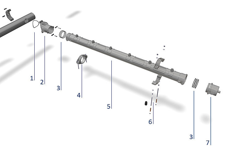
STANDARD 2 Diffusers with Separate Saddle Adapter on Round Headers
When installing STANDARD 2 diffusers, observe all general instructions issued by OTT for installation, operation and maintenance in their most recent versions (see Section 1 / yellow) along with the installation instructions given below. Install and use STANDARD 2 diffusers only as intended. Watch the STANDARD 2 installation video in its entirety and follow all procedures shown there. Also use the check list given below.
Installation Procedure
1. Remove products from packaging cartons
Remove diffusers from their packaging carton, holding each by its ends only (i.e. by gripping either A. the plastic surfaces within or B. the part of the membrane which is turned back over the clamp band; do not touch any other part of the membrane). Take care not to hit diffusers against nearby objects as this could cause damage to their membranes.
2. Drill air supply holes

At each location along the header where STANDARD 2 diffusers will be installed, drill two 20 mm (0.8") diameter holes facing each other at the 3 o'clock position and the 9 o'clock position as shown at left.
3. Place saddle adapter

This STANDARD 2 version is supplied with a separate saddle adapter as shown at left. Its bolts, nuts and sealing rings (2 bolts, 2 nuts and 2 washers for each diffuser pair) are included in the packaging carton.
Be certain that a sealing ring is placed in proper position on each side of the saddle.

Ensure that the arrows on both adapter halves are on the top.
4. Tighten mounting bolts

Using a torque wrench set at 20 Nm (15 ft lb), tighten the bolts in alternating incremental sequence, i.e. tighten the upper bolt slightly and then tighten the lower bolt slightly, repeating the sequence until the pre-set torque is attained on both bolts.
5. Place and tighten diffusers

Screw down the diffuser with a torque wrench set to 35 Nm (26 ft lb). After applying this torque, if the lengthwise blue line on the diffuser's membrane is not facing straight up (exactly at "12 o'clock"), apply increased torque - not exceeding a maximum of 45 Nm (33 ft lb) - as required to bring the lengthwise blue line to 12 o'clock. When applying the torque, hold the free end of the diffuser in place to prevent it from bending.
Tools

STANDARD 2
(article number: 4260000000)

(article number: 4100010000)

(article number 4100014000)
STANDARD 2 Diffusers on Square Headers
When installing STANDARD 2 diffusers, observe all general instructions issued by OTT for installation, operation and maintenance in their most recent versions (see Section 1 / yellow) along with the installation instructions given below. Install and use STANDARD 2 diffusers only as intended. Watch the STANDARD 2 installation video in its entirety and follow all procedures shown there. Also use the check list given below.
STANDARD 2 on different air supply holes


Installation Procedure
1. Remove products from packaging cartons
Remove the diffusers from their packaging cartons, taking care to hold each by its ends only (i.e. by gripping either A. the plastic surfaces within or B. the part of the membrane which is turned back over the clamp band; do not touch any other part of the membrane). Take care not to hit diffusers against nearby objects as this can cause damage to their membranes.
2. Drill air supply holes

At each location along the header where STANDARD 2 diffusers will be installed, drill two air supply holes facing each other at the 3 o'clock position and the 9 o'clock position as shown at left.
3. Screw in connector

Screw a connector firmly by hand into a STANDARD 2 diffuser, again taking care not to hold the diffuser by its membrane (as described above). Insert the connector through the holes in the header.
4. Screw diffuser pair together

Screw another STANDARD 2 diffuser, again taking care not to hold it by its membrane, firmly by hand onto the other end of the connector.
5. Tighten Diffusers

Screw down the diffuser (while having another installer firmly hold the diffuser on the opposite side to prevent it from turning) using a torque wrench set to 35 Nm (26 ft lb). After applying this torque, if the lengthwise blue line on the diffuser's membrane is not facing straight up (exactly at "12 o'clock"), apply increased torque - not exceeding a maximum of 45 Nm (33 ft lb) - as required to bring the lengthwise blue line to 12 o'clock. When applying the torque, hold the free end of the diffuser in place to prevent it from bending.
Tools
STANDARD 2
(article number: 4260000000)
(article number: 4100010000)

STANDARD 2 connectors
(screwing aid – only required for PP connectors)
(article number: 4261000000)
Installation / Removal of Adapter Sleeve
The adapter sleeve for the STANDARD 2 diffuser is exchangeable. To change the adapter sleeve, use pliers to pull the pre-installed adapter sleeve out of the diffuser body. Then press the new sleeve firmly into the diffuser body. Also refer to the STANDARD 2 adapter sleeve installation/removal video.


MAGNUM® Diffusers
When installing MAGNUM® diffusers, observe all general instructions issued by OTT for installation, operation and maintenance in their most recent versions (see Section 1 / yellow) along with the installation instructions given below. Install and use MAGNUM® diffusers only as intended. Watch the MAGNUM® installation video in its entirety and follow all procedures shown there. Also use the check list given below
Installation Procedure
1. Removal from packaging cartons
Remove the diffusers from their packaging cartons, taking care to hold each by its center section only. Take care not to hit diffusers against nearby objects, as this can cause damage to their membranes.
2. Placement of diffuser on header

Holding the diffuser by its center section only, make sure that the small round PP material seal on the center section faces you (i.e. exactly upwards) and that the CLIPIN® locking latch is positioned perpendicular to the lengthwise axis of the diffuser. Tilt the diffuser slightly from horizontal and laterally slip its CLIPIN® locking latch through the receiver hole in the header.
3. Fixing of diffuser on header

Holding the diffuser by its center section only, push it downwards firmly onto the header, mating the seal and the support base of the diffuser with the upper surface of the header.
4. Tightening of CLIPIN® connector

Using a torque wrench set to 27 Nm, tighten down the nut of the CLIPIN® connector.
Powered torque wrenches may also be used but only if the model intended for use is specifically approved by OTT in advance. Do not use non-approved powered tightening tools as they can cause the locking latch to slip out of its end stops or cause the threading to seize.
If you are re-installing the diffuser (installing the diffuser "used", i.e. not in new condition), reduce the torque wrench setting to 22 Nm. When re-installing diffusers, we recommend replacing (i.e. using only new) the CLIPIN® locking latches and seals.
Tools
(article number: 4100010000)

(article number: 4100011100)
MAGNUM® Dummy Plugs
When installing MAGNUM® dummy plugs, observe all general instructions issued by OTT for installation, operation and maintenance in their most recent versions (see Section 1 / yellow) along with the installation instructions given below. Install and use MAGNUM® dummy plugs only as intended. Watch the MAGNUM® installation video in its entirety and follow all procedures shown there. Also use the check list given below.
Prior to Installation
Before installation make certain that all components are dry and free of grease and other lubricants. If this is not the case, inaccurate torque application in tightening can result.
Installation Procedure
1. Positioning of dummy plug

Bring the dummy plug in position, tilting it slightly from horizontal. Laterally slip its locking latch through the receiver hole in the header.
2. Placement

Check to ensure correct positioning of the sealing ring and then press the dummy plug firmly downwards onto the receiver hole to be plugged.
3. Tightening

Using a torque wrench set to 20 Nm and a hexagonal socket spanner, slowly screw down the dummy plug until this torque is attained. Do not overtighten!
Tools
(article number: 4100010000)
(article number 4100014000)
MAGNUM® Diffusers on AirRex® Headers
When installing MAGNUM® diffusers on AirRex® headers, observe all general instructions issued by OTT for installation, operation and maintenance in their most recent versions (see Section 1 / yellow) along with the installation instructions given below. Install and use MAGNUM® diffusers only as intended. Watch the installation video in its entirety and follow all procedures shown there. Also use the check list given below.
Be certain that all components are dry when installed!

- Assembly tool for AirRex® MAGNUM® securing nut (Article number: 9555000000)
- AirRex® MAGNUM® securing nut, tightening torque 25 Nm (Article number: 4190000000)
- AirRex® MAGNUM® securing nut "O" ring
- MAGNUM® diffuser module, AirRex® version
- Double-threaded connector sleeve, tightening torque 30 Nm (Article number: 4199000000 (BSP))
- Torque wrench ⅜″ (Article number: 4100010000)
- Installation spanner for connector sleeve (Article number: 9555500000)
- Upper "O" ring for connector sleeve
- Lower "O" ring for connector sleeve
MAGNUM® AirRex® assembly kit without tourque wrench (Article number: 9110000000):
- Insertion tool for AirRex® anchor rods (M10)
- Assembly socket for AirRex® MAGNUM® securing nut
- Assembly driver for AirRex® connector and double nipple
- Assembly driver 17mm extra long for anchor rods
- Pincer for clamps (AirRex® and diffusers)
- Assembly aid für AirRex® modules

(article number: 9110000000)
(article number: 4100010000)
MAGNUM® POD Modules
When installing MAGNUM® POD modules, observe all general instructions issued by OTT for installation, operation and maintenance (see Section1/yellow) in their most recent versions along with the installation instructions given below. Install and use MAGNUM® POD modules only as intended.
Steps in Installation
1. Installation of lateral

Place all headers on basin floor as shown in the layout drawing. Using the header as a template, mark the required anchor rod positions on the basin floor. Set the header aside. Drill mounting holes vertically in the marked positions to required depth. Install a stainless-steel anchor rod in each mounting hole, using a suitable fixing element (e.g. resin-based anchor) to fix the rod in the base of the hole.
Place a nut and washer on each anchor rod and screw to required height. Place the header over the anchor rods, resting it on the washers.
Using the anchor-rod threading and the level bulbs, fine adjust the height of each nut as required to achieve exactly level alignment. Place washer and nut over each rod and screw down tightly.
2. Connection to Air Supply Line

All air supply lines must installed stress-free and with close support spacing (typically at intervals of less than 2 m/ 78").
Avoid any crossing-over of lines or contact between lines. If several lines are bundled and held by common supports, make certain that this does not damage them in any way.
When cutting pipe segments to the exact lengths required for the air supply line, take into account changes in length due to temperature (i.e. thermal expansion/contraction) and other operating conditions.
3. Installation of Diffusers

Before installing diffusers, clean out the air supply system (all lines from the blowers to the diffusers) by thorough air purging.
Make certain that all diffusers have sufficient clearance to neighbouring diffusers, lines, agitators, basin walls etc.
Install and start up MAGNUM® diffusers in accordance with installation, operation and maintenance instructions for MAGNUM® diffusers (available separately from OTT).
OTT Membranes (except profile membranes)
When installing OTT membranes, observe all general instructions issued by OTT for installation, operation and maintenance in their most recent versions (see Section 1 / yellow) along with the installation instructions given below. Install and use OTT membranes only as intended. Watch the membrane installation video in its entirety and follow all procedures shown there. Also use the check list given below.
Installation Procedure
1. Remove old membranes.

Carefully remove the clamp bands and pull the membranes off of the diffuser bodies. Do not slit or cut the old membranes when removing them as this could create sharp edges on the diffuser bodies.
2. Clean diffuser bodies.

Use a cloth to dry off all diffuser bodies, cleaning off as well any foreign materials.
3. Place and mount new membranes.

Holding the new membrane by both ends, push it over the diffuser body. Lead the membrane with your front hand and push it with your rear hand.
Turn the membrane so that its blue line is pointing exactly upwards, i.e. at "12 o’clock".
4. Install and lock clamp bands

Bring the ear clamp bands into position and lock them in place with the OTT installation pliers supplied.


Pincer for ear clamps (Article number: 4410000000)
OTT Profile Membranes
When installing OTT membranes, observe all general instructions issued by OTT for installation, operation and maintenance in their most recent versions (see Section 1 / yellow) along with the installation instructions given below. Install and use OTT membranes only as intended. Watch the membrane installation video in its entirety and follow all procedures shown there. Also use the check list given below.
Installation Procedure
1. Remove old membranes.

Carefully remove the clamp bands and pull the membranes off of the diffuser bodies. Do not slit or cut the old membranes when removing them as this could create sharp edges on the diffuser bodies.
2. Clean diffuser bodies

Use a cloth to dry off all diffuser bodies, cleaning off as well any foreign materials.
3. Installing the profile seals

Locate the profile seals exactly at the top (12 o'clock position) on both ends of the diffuser, opposite the air channel. Allow a gap of 3 mm (0.1") between the profile seal and the end of the diffuser.

To simplify installation, one side of the profile seals is self-adhesive.
4. Mounting and securing the new membranes

Grasp the membranes at both ends and slide them onto the carrier body. The front hand guides the membranes, while the back hand pushes the tube onto the carrier body.

Align the membranes so that the profile contour engages in the groove of the profile seal.

5. Installing the clamping collars

Now mount the 1-ear clamps such that they press the membrane onto the profile seal.

Secure them using the special OTT pliers.

Fold the membrane over so that it covers the 1-ear clamp.
Pincer for ear clamps (Article number: 4410000000)
Guardrails
OTT guardrails are used to securely hold diffusers in place near agitators, weirs, gate valves, inlet or outlet channels or other locations where high-speed or turbulent flow can occur. When installing OTT guardrails, observe all general instructions issued by OTT for installation, operation and maintenance in their most recent versions (see Section 1 / yellow) along with the installation instructions given below. Install and use OTT guardrails only as intended. Also use the check list given below in Section 2.13.
Prior to Installation
Required Components and Tools
The following components are required for installation:
- Guardrails ("L" rails 30mm x 30mm x 4mm / 1.18" x 1.18"x 0.16")
- Guard caps (blue)
- M8 nuts and washers for guard caps
- M8 threaded anchor rods with nuts and washers for mounting of guardrails on basin floor
- Fixing elements (e.g. resin-based anchors), used to fix anchor rod in base of each mounting hole
Required tools:
- Wrench (spanner) for M8 bolts
- Electric percussion drill with 10 mm diameter bit (bit length: 50 cm)
Pre-Installation Check
Before mounting the guardrails, make certain that the diffusers they will secure have been installed in accordance with OTT’s installation instructions.
1. Installation of Guard Caps

Mounting of Guard Caps; Joining Guardrail to Diffusers
Mount the OTT guard caps in their receiving holes in the guardrail. Insert the mounted guard caps into the ends of the diffusers to be secured, thereby joining the guardrail, the diffusers and the header in a "ladder configuration".
Drilling of Mounting Holes for Threaded Anchor Rods
Holding the guardrail in this position, use it as a template to mark (vertically through the receiving holes in the guardrail for the threaded anchor rods) the locations of the mounting holes to be drilled for the threaded anchor rods.
Drill the mounting holes to the required depth into the basin floor, taking care to drill them exactly vertically.
2. Installation of Guardrail

Mounting of Guardrail
Place a fixing element in the drilled mounting hole for the threaded anchor rod. Insert the threaded anchor rod through its receiving hole in the guardrail. Place a washer and then a nut on the lower end of the rod, screwing the nut upwards to the approximate height required to hold the guardrail in place from below. Repeat the procedure for each drilled mounting hole and threaded anchor rod.
Then insert each rod to the bottom of its drilled mounting hole, i.e. all the way into its fixing element. Allow setting time as specified by the fixing element manufacturer. Then adjust the height of each nut as required so that the guardrail holds the diffusers exactly level (i.e. horizontal). Then place a washer and a nut over each anchor rod, screwing the nut downward tightly against the guardrail to fix it in place from above.
3. Final Check

AirRex® / AirRex+® with Adapter for Pipe Socket
When installing AirRex® headers, observe all general instructions issued by OTT for installation, operation and maintenance in their most recent versions (see Section 1 / yellow) along with the installation instructions given below. Install and use AirRex® headers only as intended. Watch the AirRex® headers installation video in its entirety and follow all procedures shown there. Also use the check list given below in the last section of these installation instructions.

- AirRex® ear clamp band
- AirRex® flexible transition tube
- AirRex® Adapter for Pipe Socket
- AirRex® seal set
- AirRex® twin-shell mounting clamp
- AirRex® module
- AirRex® installation hardware including anchor-rod fixing elements
- AirRex® end cap
Preparation Before Installation
Install AirRex® modules only after all work on the basin has been completed. Be certain that all outlet sockets of the air-supply pipes have been installed at the correct height, i.e. the height which will result in the desired height of the installed diffusers.
Outside diameter A of pipe socket

| AirRex® Adapter for Pipe Socket DN 50 | 60,3 mm | 23.75" |
| AirRex® Adapter for Pipe Socket DN 65 | 76,1 mm | 29.96" |
| AirRex® Adapter for Pipe Socket DN 80 | 88,9 mm | 35" |
| AirRex® Adapter for Pipe Socket DN 100 | 114,3 mm | 45" |
Drilling of Mounting Holes for Anchor Rods

Drill two mounting holes for the first AirRex® mounting clamp at a distance of 370 mm (14.6") from the air supply line's outlet socket (see illustration above). The diameter and depth of these holes are based on the supplied specifications by the manufacturer of the resin-based anchor used. The holes for the second AirRex® clamp are set at a distance of 1270 mm (50") from the first one (1300 mm (51.2") when using AirRex+® modules with 8 diffuser connections). Drill all further mounting hole pairs a distance of 1815 mm (72.45") from the preceding holes. All mounting holes must be exactly in line and perpendicular to the basin floor! All hole separations given are center-to-center distances.
Then, place a resin-based anchor (cartridge or injected dab) in the bottom of each hole and insert its anchor rod fully downwards. Be certain to observe the supplied anchor manufacturer's installation and use instructions (in particular instructions for screwing the anchor rod into the anchor to ensure proper resin mixing and distribution).
Keep each anchor rod positioned exactly perpendicular to the basin floor until the resin has hardened.
Mounting and Alignment of Lower Shells

Screw a support nut onto each anchor rod to the required height and place a washer on top of each support nut. Place a lower shell (i.e. lower half of twin-shell mounting clamp) over the first two anchor rods and move it downward so that it rests on their washers / support nuts. Use the same procedure to place the other lower shells on their anchor rods in the line. Use a bubble level or equivalent to check for level positioning (both lengthwise and perpendicular to the line axis) of all lower shells and correct nut heights as necessary.
Installation of AirRex® Modules

Place the first AirRex® module (supplied with factory-mounted adapter) in the first two lower shells. Slip the AirRex® flexible transition tube over the AirRex® adapter and use an ear clamp band (supplied with the modules) to fix the flexible transition tube in place.

Now push the AirRex module towards the air supply line, slipping its transition tube over the outlet socket.

Now place the upper shells of the first two clamps on the threaded rods so that they correctly interlock with the pipe at 12 o'clock. Then place a washer on the anchor rod on each side and screw a nut in place, hand-tight.

Now pull the AirRex® module back through the mounting clamps, i.e. away from the air supply line, until its end stop ridges contact the left side of the first mounting clamp (as shown below, see blue arrow). Measure the gap between the outlet socket and the AirRex® connector piece. This gap must be within a range of 5 - 10 mm (0.2" - 0.4").

After checking to ensure that the gap between the outlet socket and the AirRex® adapter is within this range, leave the module in position - i.e. with its end stop ridges still in contact with the mounting clamp - and use an ear clamp band (supplied with the modules) to fix the transition tube in position on the outlet socket as shown above.

Use a torque wrench set at 20 Nm (15 ftlb) to tighten down the nuts on the first two mounting clamps.

Using the supplied assembly paste (use no other pastes of any kind), thoroughly lubricate the seals of the next AirRex® module. Install it by placing it in the lower shells of the next two mounting clamps, pushing it into the module last installed and then turning it to close the bayonet joint. Repeat the procedure for the other AirRex® modules to be installed in the line.

Fit the other top shells of the clamps, again correctly interlocking at 12 o'clock, place a washer and screw a nut over the two anchor rods of each clamp. Tighten the nut with a tightening torque of 20 Nm (15 ftlb). Cap off the last module of the line with an AirRex® end cap. Install the end cap using the same procedure as used for the modules, i.e. by thoroughly lubricating its seals with the supplied assembly paste, pushing it into the module last installed and then turning it to close the bayonet joint.
Again use a bubble level or equivalent to check that the AirRex® line is level over its entire length, correcting the shell heights by adjusting their nuts as required. Retighten any nut adjusted using a torque wrench set to 20 Nm (15 ftlb).
Tools

(Article number: 4410000000)

(article number: 9565500000)
(article number: 4100010000)
AirRex® / AirRex+® with Adapter for Round Header with Drill Hole
When installing AirRex® headers, observe all general instructions issued by OTT for installation, operation and maintenance in their most recent versions (see Section 1 / yellow) along with the installation instructions given below. Install and use AirRex® headers only as intended. Watch the AirRex® headers installation video in its entirety and follow all procedures shown there. Also use the check list given below in the last section of these installation instructions.
- AirRex® connection adapter seal
- AirRex® connection adapter for round cross-section pipe with drill hole
- AirRex® seal set
- AirRex® clamp
- AirRex® module
- Anchor rod set incl. composite anchor
- AirRex® end cap
Preparation Before Installation
Install AirRex® modules only after all work on the basin has been completed. Be certain that all outlet sockets of the air-supply pipes have been installed at the correct height, i.e. the height which will result in the desired height of the installed diffusers.

The bore in the round cross-section header must have a diameter of 114 mm (4.49").
Drilling of Mounting Holes for Anchor Rods

Drill two mounting holes for the first AirRex® mounting clamp at a distance of 360 mm (14.2") from the air supply line's outlet socket (see illustration above). The diameter and depth of these holes are based on the supplied specifications by the manufacturer of the resin-based anchors used. The holes for the second AirRex® clamp are set at a distance of 1270 mm (50") from the first one (1300 mm (51.2") when using AirRex+® modules with 8 diffuser connections). Drill all further mounting hole pairs a distance of 1815 mm (72.45") from the preceding holes. All mounting holes must be exactly in line and perpendicular to the basin floor! All hole separations given are center-to-center distances.
Then, place a resin-based anchor (cartridge or injected dab) in the bottom of each hole and insert its anchor rod fully downwards. Be certain to observe the supplied anchor manufacturer's installation and use instructions (in particular instructions for screwing the anchor rod into the anchor to ensure proper resin mixing and distribution).
Keep each anchor rod positioned exactly perpendicular to the basin floor until the resin has hardened.
Mounting and Alignment of Lower Shells

Screw a support nut onto each anchor rod to the required height and place a washer on top of each support nut. Place a lower shell (i.e. lower half of twin-shell mounting clamp) over the first two anchor rods and move it downward so that it rests on their washers / support nuts. Use the same procedure to place the other lower shells on their anchor rods in the line. Use a bubble level or equivalent to check for level positioning (both lengthwise and perpendicular to the line axis) of all lower shells and correct nut heights as necessary.
Installation of the AirRex® Adapter for Round Header with Drill Hole

Position the connection adapter together with the seal on the hole in the round cross-section pipe header. On the opposite side, position the clamp and assemble it onto the connection adapter with the fastening set.

Tighten the two screws with a tightening torque of 30 Nm.
Installation of AirRex® Modules

Lubricate the seals of the first AirRex® module with the assembly paste supplied. Insert the first module into the bottom shells of the first two clamps.

Now push the module into the adapter and turn it until the bayonet catch engages.

Now place the upper shells of the first two clamps on the threaded rods so that they correctly interlock with the pipe at 12 o'clock. Then place a washer on the anchor rod on each side and screw a nut in place. Tighten the nuts firmly with a torque of 20 Nm.

Now connect the other AirRex® modules. To do this, first lubricate the seals with the assembly paste supplied. Then push the module into the previous module and turn it until the bayonet catch engages. For lubrication, use exclusively the assembly paste supplied.

Fit the other top shells of the clamps, again correctly interlocking at 12 o'clock, place a washer and screw a nut over the two anchor rods of each clamp. Tighten the nut with a tightening torque of 20 Nm. Close the last module of an AirRex® line with an AirRex® end cap. The end cap is attached in the same way as the modules, i.e., its seal set has to be lubricated with the assembly paste supplied, pushed into the last AirRex® module and turned until the bayonet catch engages.
Check again using a spirit level or a similar tool to make sure that the AirRex® line is level over its entire length, and correct the clamp heights as required. Retighten any readjusted nut to a tightening torque of 20 Nm.
Tools
(article number: 9565500000)
(article number: 4100010000)
(article number 4100014000)
AirRex® Dummy Plugs
When installing AirRex® dummy plugs, observe all general instructions issued by OTT for installation, operation and maintenance in their most recent versions (see Section 1 / yellow) along with the installation instructions given below. Install and use AirRex® dummy plugs only as intended. Also use the check list given below in Section 2.13. Be certain that all components are dry when installed!

- Torque wrench ⅜″ (Article number: 4100010000)
- 20 mm socket spanner for 20 mm dummy plug
- Dummy plug, tightening torque 20 Nm (Article number: 90114000013 (BSP))
- "O" ring
- AirRex® module (Article number: 9111000000 (BSP))
D-REX® Disc Diffusers
When installing D-REX® disc diffusers, observe all general instructions issued by OTT for installation, operation and maintenance in their most recent versions (see Section 1 / yellow) along with the installation instructions given below. Install and use D-REX® disc diffusers only as intended. Also use the check list given below.
Be certain that all components are dry when installed!

- D-REX® membrane
- D-REX® diffuser body
- D-REX® support ring
- D-REX® double-threaded nipple


Tools

(article number: 9555500000)
(article number: 4100010000)
D-REX® Disc Diffusers on Round Cross-Section Pipe Headers
The instructions in Part 1 (yellow) of OTT's latest version of the general installation, operating and maintenance instructions always apply to the installation of the D-REX disc diffusers. The diffusers may only be used and installed in the manner intended. Please also observe the information in the installation video for this product. During installation, make additional use of the check list.
Work steps
1. Drilling the holes

To install D-REX disc diffusers on round cross-section pipe headers, a hole must be drilled in the headers at the 12 o'clock bottom position.
The hole diameter is 20 mm (0.8").
2. Inserting the saddle-contoured adapter

The saddle-contoured adapter is pre-assembled at the factory, whereas the bolts, nuts and gaskets are provided separately in the box.
Make sure that a gasket is inserted into both sides of the saddle.

Ensure that the arrows on both adapter halves are on the top.
3. Tightening the fixing screws


Tighten the two fixing screws evenly. Use a torque of 20 Nm.
4. Removal from the boxes
Take the diffusers out of the boxes. To avoid damaging the membranes, make sure you do not hit any surrounding objects when unpacking.
5. Tightening the diffuser

Screw the D-REX® onto the thread of the saddle-contoured adapter and tighten it firmly with both hands.
Tools
(item no.: 4100010000)
D-REX® Disc Diffuser with CLIPIN® Adapter
The instructions in Part 1 (yellow) of OTT's latest version of the general installation, operating and maintenance instructions always apply to the installation of the D-REX disc diffusers. The diffusers may only be used and installed in the manner intended. Please also observe the information in the installation video for this product. During installation, make additional use of the check list.
Work steps
1. Drilling the holes

To install D-REX with a CLIPIN® adapter, a hole must be drilled in the headers at the 12 o'clock bottom position.
The hole diameter is 20 mm (0.8").
2. Fitting the CLIPIN® adapter

The CLIPIN® adapter is pre-assembled at the factory.

3. Tightening the fixing screws
Tighten the two fixing screws evenly. Use a torque of 27 Nm.
4. Removal from the boxes
Take the diffusers out of the boxes. To avoid damaging the membranes, make sure you do not hit any surrounding objects when unpacking.
5. Tightening the diffuser

Screw the D-REX® onto the thread of the CLIPIN® adapter and tighten it firmly with both hands.
Tools
(item no.: 4100010000)
Installation Checklist
| Before Installation: | Yes | No |
|---|---|---|
| Were the correct products supplied in the correct quantities? | ◯ | ◯ |
| Were all packaging cartons undamaged? | ◯ | ◯ |
| Are all products in accordance with the layout drawing and the performance data sheet? | ◯ | ◯ |
| Were all packaging cartons brought unopened into the basin? | ◯ | ◯ |
| Were all products checked for damage before installation? | ◯ | ◯ |
| Were any products found to be damaged immediately set aside? | ◯ | ◯ |
| Were the air supply lines and headers properly installed, air purged and cleaned? | ◯ | ◯ |
| During Installation: | Yes | No |
|---|---|---|
| Were the products installed in accordance with OTT’s instructions? | ◯ | ◯ |
| Was the specified torque attained using a correctly set torque wrench? | ◯ | ◯ |
| Were all diffusers checked after installation to ensure proper fit on header and proper positioning on header? | ◯ | ◯ |
| After Installation of Diffusers: | Yes | No |
|---|---|---|
| Was the leak test carried out in accordance with OTT’s instructions? | ◯ | ◯ |
| Were any leaks that were found repaired? | ◯ | ◯ |
| Were the diffusers run in according to OTT’s instructions? | ◯ | ◯ |
| Was the bubble pattern tested in accordance with OTT’s instructions with successful results? | ◯ | ◯ |
_______________________________________
Signature, Date
Archive
STANDARD Diffusers
When installing STANDARD diffusers, observe all general instructions issued by OTT for installation, operation and maintenance in their most recent versions (see Section 1 / yellow) along with the installation instructions given below. Install and use STANDARD diffusers only as intended. Watch the STANDARD installation video in its entirety and follow all procedures shown there. Also use the check list given below.
Installation Procedure
1. Remove products from packaging cartons
Remove diffusers from their packaging carton, holding each by its ends only (i.e. by gripping either A. the plastic surfaces within or B. the part of the membrane which is turned back over the clamp band; do not touch any other part of the membrane). Take care not to hit diffusers against nearby objects as this could cause damage to their membranes.
2. Place diffusers on header

Screw a connector firmly by hand into a STANDARD diffuser, again taking care not to hold the diffuser by its membrane (as described above). Insert the connector through the holes in the header.
When installing onto round headers, use appropriate adapters as required.
Screw another diffuser, again taking care not to hold it by its membrane, onto the other end of the connector.
3. Fix diffuser pair in the header

Using the OTT assembly tool (assembly mandrel with socket for square-head key; supplied with the diffusers) and a square-head key, screw down each diffuser.
4. Tighten diffusers

Plastic Connector (PP)
Tighten the diffuser using an adjustable-torque wrench set at 28 Nm (21 ft lb) and the OTT assembly tool. After reaching the pre-set torque, continue turning the diffuser until its lengthwise blue line is facing straight up (exactly at "12 o'clock").
Brass/Stainless Steel Connector
Tighten the diffuser using an adjustable-torque wrench set at 45 Nm (33 ft lb) and the OTT assembly tool. After reaching the pre-set torque, continue turning the diffuser until its lengthwise blue line is facing straight up (exactly at "12 o'clock").